1st Gen Toyota 4Runner Suspension / Phase-III
![]()
Contents:
![]()
Phase III:
Well, after a year on Phase II, I found that I had pushed the stock suspension to its limits. In front, the shocks were limiting droop and with the repeated strain, one lower shock mount actually tore right off the axle (in fact, you may want to inspect your factory shock mounts, the weld quality on mine was poor and there was rust working its way under the weld). I was also not really happy with the relocated holes in the front spring perches (especially with the aluminum axle shims - center hole was in the thin end). In back, the shocks limited compression in their stock location.
So, instead of simply welding the broken shock mount back on, I decided to just cut everything off and start out clean. I took this opportunity to rebuild the front axle (it was leaking gear oil badly due to an improperly positioned MarTack), and after removing the broken right shock mount, decided the left one had to go as well, and while the grinder was out, I cut off those silly sway bar end link brackets and that useless torque rod bracket.
[Return to the top]Front:
Custom Springs:
So, I put the rear springs back to the original NWOR setup (temporarily - in order to free up my stock rear leaves) and then acquired a rear spring pack from an '83 short bed pickup (thanks to Barney McNamara for that). The pickup springs had about 3" extra free arch than my 4Runner springs (8" vs. 5"), so I made use of the three main p/u leaves, then the 3rd and 4th leaves from my stock 4Runner pack then initially I used the 4th (1st overload) leaf from the p/u pack. Later I took the 2nd 4Runner leaf, cut off the mil-wrap end, cut it in two at the center hole, making two leaves out of it, drilling new center holes in each half to match the other leaves. I ended up with a nice 7-leaf pack, all fairly thin and very flexible. After measuring, I found that using symmetrical springs in front resulted in a fairly level body. No need to fool with the left and right spring nonsense, aside from welding a 3/8" piece of flat stock to the driver's side perch to reinforce it and raise it level with the passenger side perch.
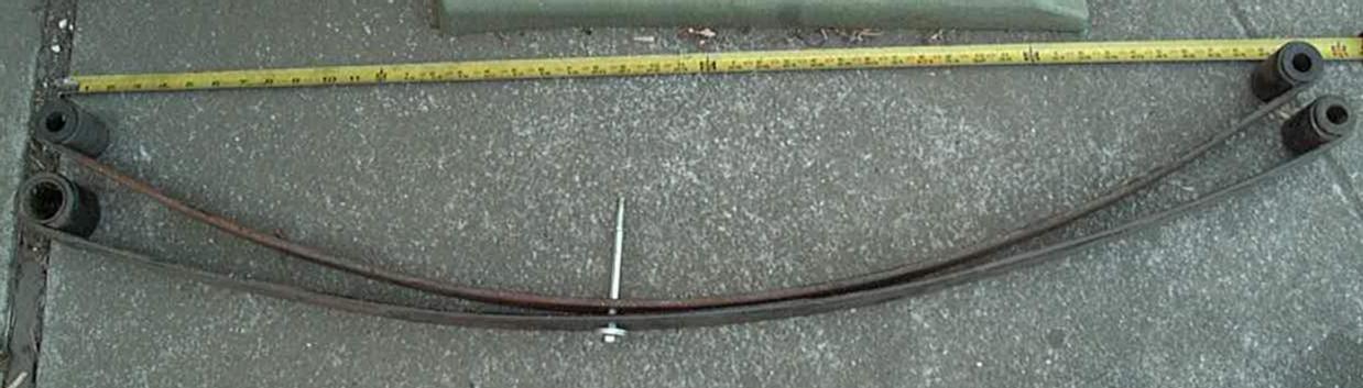
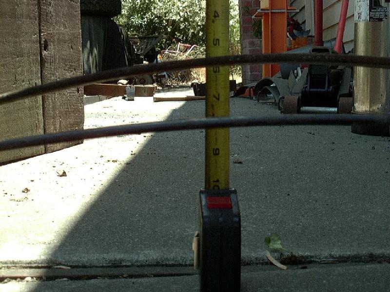
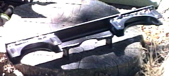
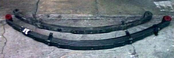
Below, you can see a side-by-side comparison of the main leaf from an '83 Toyota pickup rear spring pack and the same leaf from an '85 4Runner. The early model springs used the small eyes on both ends but more importantly had nearly 3" more free arch than the 4Runner leaves. I'm not sure if this was a pickup vs. 4Runner difference, an '83 vs. 85 difference, but whatever the reason, I prefer the '83 rear spring pack, at least the upper 3 leaves, anyway.
- Update:
-
I later modified this spring pack after I lowered my front spring
hangers. I took out the two short leaves I had made by cutting an old
4Runner leaf in half and replaced it with the lowest overload leaf from
the pickup pack. This leaf is arched a bit, then painted everything
with two coats of Slip Plate graphite paint. So my front spring pack
now consists of the upper 3 leaves from an '83 Toyota pickup rear
spring (locates the axle 2" forward), the 3rd (long) leaf from an
'85 4Runner rear spring. and the 5th (overload) leaf from an '83 pickup
rear end, 5 leaves in total. With the lowered spring hanger up front
giving me an unwanted 2" lift, the reduced spring pack reduced the
ride height 2" to get me back to my original height.
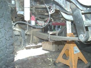
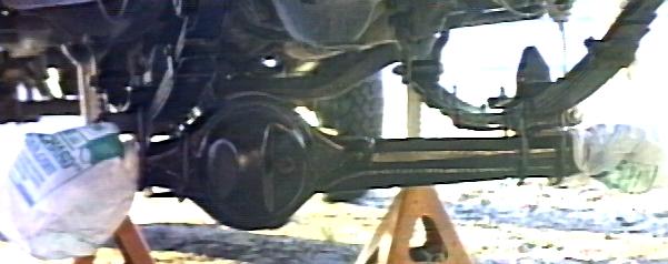
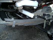
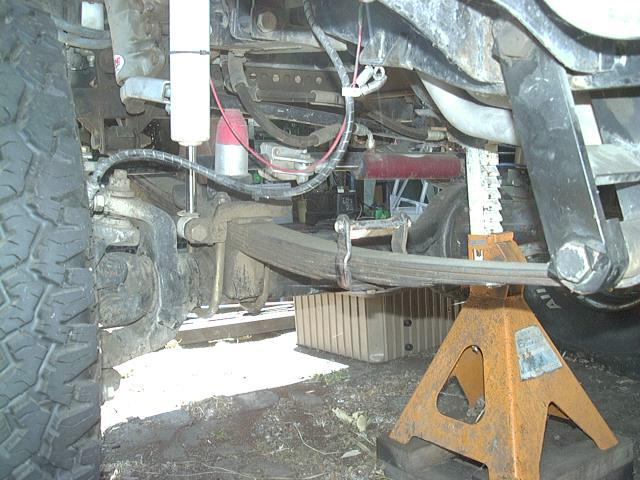
- FYI: In the above photos, the stainless steel brake lines are approx. 26" in length along with a lowered hardline bracket and give plenty of length to handle the full spring droop.
- Update-part2:
-
Note to self: overload leaves make a spring pack very stiff! So, after
testing the 5-leaf pack out I found the short-stiff overload was
causing the pack to be too stiff and it looked like it was going to
kink the longer leaves, since it didn't bend at the tip. So, time for
another plan...
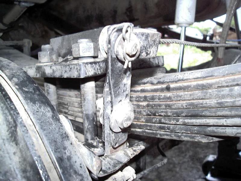
- I had been kicking the idea of making an anti-wrap leaf for my front springs like the rear Alcan's had. Basically an anti-wrap leaf is a half-leaf that sits on top of the spring pack with a clamp that goes under the springs. As the axle tries to tip down in back from the torque reaction at the wheels, the anti-wrap leaf resists that torque by lifting at the front of the springs. I had the original 7 leaves I originally ran and I wanted to end up with 6 load leaves, so I chose the modified rear 4Runner leaf (the one I had cut the mil-wraps off of) and cut it in half, about 3.5" behind the center bolt hole. Then, I removed the bolted-on spring clamp and flipped it over, same with the spring anti-friction pad. Then, to match the arch of the pickup leaves, I ran this leaf through my press to give it some more arch and then clamped it, and the remaining 6 leaves into a pack consisting of:
- Anti-wrap leaf - '85 4Runner rear #2 leaf minus mil-wrap front half (see image below):
- Main leaf - '83 pickup rear #1 leaf
- 2nd leaf - '83 pickup rear #2 leaf
- 3rd leaf - '83 pickup rear #3 leaf
- 4th leaf - '85 4Runner rear #3 leaf
- 5th leaf - '85 4Runner rear #4 leaf; long half (cut at center bolt hole)
- 6th leaf - '85 4Runner rear #4 leaf; short half (cut at center bolt hole)
- The 5th and 6th leaves were made out of one stock leaf, which was cut in two pieces at its center bolt hole then new center bolt holes were drilled in the new centers to attach the leaves to the pack. I use two clamps to hold the leaves together, one in front that is attached to the anti-wrap leaf and one in back, see above photos.
- So, how does this spring pack work? In a word, amazing! Wheel hop seems to be a thing of the past. I had the anti-wrap leaves in back, but none up front. I used to experience a lot of wheel hop when I would start to lose traction. I had assumed that the anti-wrap leaves in back were just not doing the job of controlling hop very well. WRONG! It was the lack of anti-wrap up front that would start the hop, then when the front axle unloaded, the rear axle would take the full torque, wind up and hop, etc. Now that the front and rear are equally controlled, I can now ease off the throttle when I lose traction, let all 4 wheels turn slowly, while I work the steering searching for traction. Its really neat to be apparently hung up on an obstacle, but with some subtle steering input, you work your way free and continue on your way.
- Important Note: After about 12 years of use, I experienced a broken front main leaf. After examining the break, I traced it's cause to a rather sharp corner on the back end of the anti-wrap leaf that sits on top of the main leaf. While I had taken care to soften the upper ends of leaves I had put lower in the spring part, to minimize stresses where the end of a lower leaf contacts the leaf above it as the spring compresses, I neglected to do the same for the bottom end of the half-length anti-wrap leaf. As it ended just past the end of the spring plate (which does have a softened edge) the main leaf would tend to bend just at the rear end of that cut leaf. Now this only happens under droop and I simply forgot to take that into account. So after replacing the broken main leaf, I took out the anti-wrap leaf and ground a gradual radius on the end, starting about 1" from the end and rounding up through the thickness of the leaf. Hopefully, this will make this set of main leaves last for many years.
- I had been kicking the idea of making an anti-wrap leaf for my front springs like the rear Alcan's had. Basically an anti-wrap leaf is a half-leaf that sits on top of the spring pack with a clamp that goes under the springs. As the axle tries to tip down in back from the torque reaction at the wheels, the anti-wrap leaf resists that torque by lifting at the front of the springs. I had the original 7 leaves I originally ran and I wanted to end up with 6 load leaves, so I chose the modified rear 4Runner leaf (the one I had cut the mil-wraps off of) and cut it in half, about 3.5" behind the center bolt hole. Then, I removed the bolted-on spring clamp and flipped it over, same with the spring anti-friction pad. Then, to match the arch of the pickup leaves, I ran this leaf through my press to give it some more arch and then clamped it, and the remaining 6 leaves into a pack consisting of:
-
Update-part3:
To finish up the design and correct the problem of the springs hitting the pitman arm on the steering box, I went with a dropped front spring hanger (2.5" drop from stock) and went to 3.5" longer than stock front shackles to correct the caster angle for steering. Bump stops have been changed a little and I'm still working on getting them set to my satisfaction.
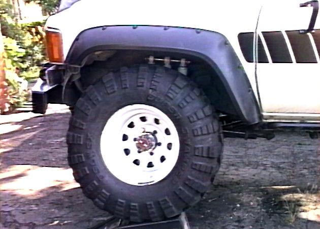
So what did all this work get me, lift-wise? When I first measured the front wheels wells on my nearly stock 4Runner, I got 36" running on 30" tires. Now, after a 3" body lift and 33" tires (1.5" lift at the axle) I get a 44" fender height, a difference of 8" from stock. Subtracting the 3" body lift and 1.5" due to the taller tires and I see 3.5" of lift from the suspension. However, most of that is due to the longer shackle (3.5") and dropped spring hanger (2.5"), which average to 3" of static lift. So, subtracting that 3" leaves 1/2" of spring lift! Not surprised, the spring pack is nearly flat. I may ultimately add a 7th load leaf to the pack for a bit of lift.
- Footnotes:
-
To my knowledge, this spring pack is among the first in the US to use
stock rear springs for a front suspension. I got the idea from the old
Toy4x4 mailing list from a poster in Australia. And note, that due to
the thickness of the resulting spring pack, it is unlikely that you can
do a Rear Up Front (RUF) spring swap like this with stock steering, due
to the clearance issues with the driver's side steering arm and the
springs/u-bolts, at least without some modifications. I already had a crossover
steering setup installed, so that was not an issue in my case.
- The question comes up how do you decide how to build a spring pack out of more that one set of springs. I found it useful to tear apart a few sets of springs and see how they are built and how they work. Take each leaf out, flip it upside down (arch up) and stand on it. Measure the deflection (in inches) and divide by your weight (in lbs.) and you have a crude figure of the spring rate (in lbs. per in.). Note how the top leaves are softer than the lower ones, they are also longer. Then take all the leaves you have, sort them by length, arch and rate. Put the long and more arched leaves on top. Put the shorter and stiffer leaves on the bottom. Stagger the leaf ends from long to short. Then try it out. If too soft, add some leaves, if too stiff, take some out. If you have one long leaf and need two short leaves, cut the long one in the middle, taper the ends if desired and see what happens.
Long Travel Shocks:
A major limiting factor in the Toyota front axle suspension is the shock absorber. With a conventional shock mount, there is an upper and lower mounting point that are fixed. At full compression, the shock should be short enough not to bottom out (bottoming out is bad) and at full droop, the shock should be long enough to not limit droop (limiting droop is bad) since either case imposes high loads on the shock and mounts, neither of which are designed for that purpose (case in point my torn off shock mount). The length of the tube of the shock is what limits compression, so ideally it should be short. The length of the rod in the shock is what limits extension, so ideally it should be long. However, in compression, the rod must go somewhere and that is into the tube. So, if you add an inch to the length of the rod (for extra extension) you must also add an inch to the tube, thereby limiting droop. In fact, for every inch you extend the rod (and tube) you loose an inch of compression, but gain 2" of extension (1" of tube plus 1" of rod = 2").
So it seems so simple, make a really long tube shock and mount it up high enough to allow the springs to fully compress. However, there is a wheel well located above the frame. One option is to cut a hole and run the shock up and into the engine compartment. FIne if you have room, but with EFI, power steering, on-board air and welder, I have no place to go up, plus I like the idea of keeping the engine compartment reasonably isolated from the dust and mud thrown up from the tires. So, if a single long shock is out of the question, how about folding one in two to create a moveable shock mount?
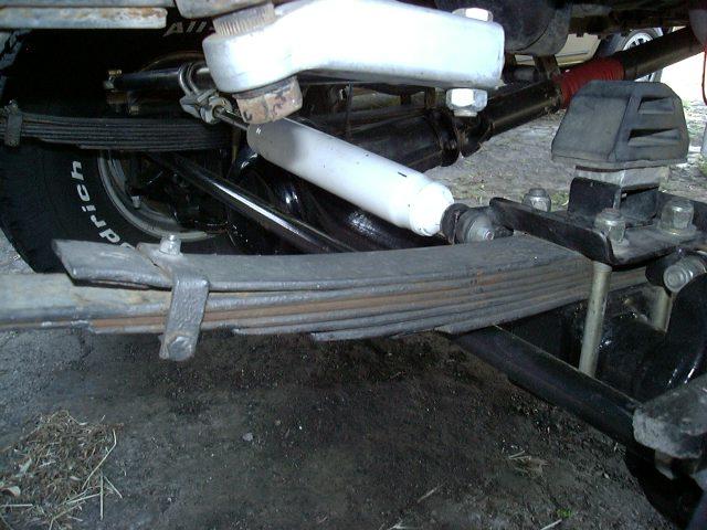
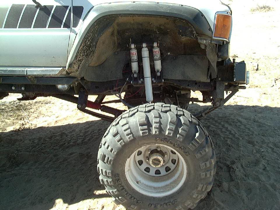
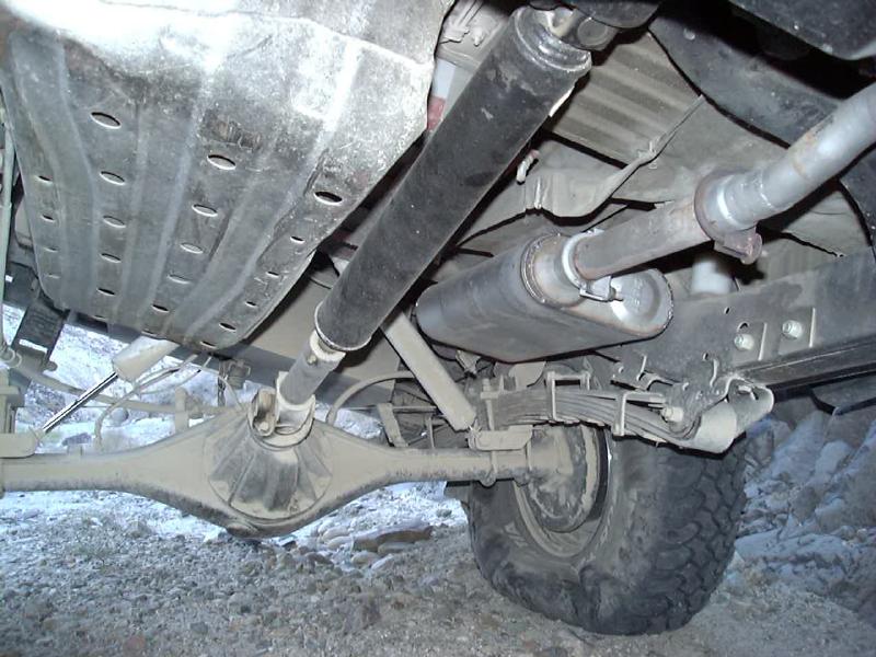
I saw a really trick looking long-travel triple shock concept from James Stevenson. He uses this in race trucks that have rules preventing body alterations for things like long shocks. So, I modified the design for my front axle to prevent the shocks from limiting travel. In addition it allows for re-centering the shock on the axle that now lives 2" (and later 2.75") ahead of it's stock location. The shock mount plate is fully bolted on to avoid welding on this critical part of the frame. The base plate serves as an enlarged and relocated contact area for the bumpstop attached to the top-mounted spring u-bolt plate. Finally, the two through-bolts that hold it to the frame serve as handy ground points for my dual battery wiring (1/0 cable lugs need solid anchor bolts) and also hold my motor mount retaining chains to the frame. The two short shocks on the sides are Rancho 9120's, approx. 10" compressed length and 14" extended length and approx. 4.68" travel. In the newer Rancho 9000XL part numbers, that equates to a 99120 shock.
I later swapped the Rancho 9010s (pictured above) for some l-o-n-g Rancho 9012s shocks which provide adequate travel when mounted to the pair of 9120s. This nets me about 18.5" of vertical front shock travel (13.97 + 4.68 = 18.65"), which should last me for a while :-) I hope to have an inch or two of unused travel at the top and bottom. With the 2.5" spring hanger drop, I've increase my down-travel nearly 2" and should still have the same up-travel. Also, in changing from a 1" to a 3" body lift, I was able to raise the lower end of the auxiliary shocks by 2" and pushed them in closer to the frame to boot. The whole idea of this design is to eliminate any shock limits of both up and down travel. Another side benefit of this design is that it eliminates the excessive leverage on the frame caused by a rigid "longer than stock" shock mount. This is an important consideration and is part of the design concept.
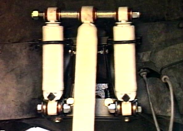
Here's a closeup of the upper mount. The basic idea with this design is that the upper shock mount floats up and down. An added benefit is that the main shock loads are transferred directly to the frame and there are not the heavy twisting forces you get with a tall shock tower. The tops of the three shocks are connected with a piece of 3/4" hardened steel rod, currently with hitch pins on the end to hold everything in place. I also remounted the main shock with the can down (rather than up) to keep the adjustment knob out of harms way. Later I converted the manual adjuster over to the air-operated remote control system and am really happy with that. The auxiliary shocks are left at the lowest setting all the time.
Shock Towers, v2.0
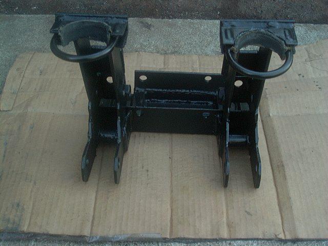
After many years of use with the above setup and a few minor modifications to the design (that probably weakened it) I had problems with the upper u-bolt clamp brackets fatiguing and breaking. That was the one part of the design I was not totally happy with. So prompted by the breakage, I decided to "do it right" this time. I totally abandoned the stock shock bracket for support and instead made a one-piece shock tower to support everything:
 |
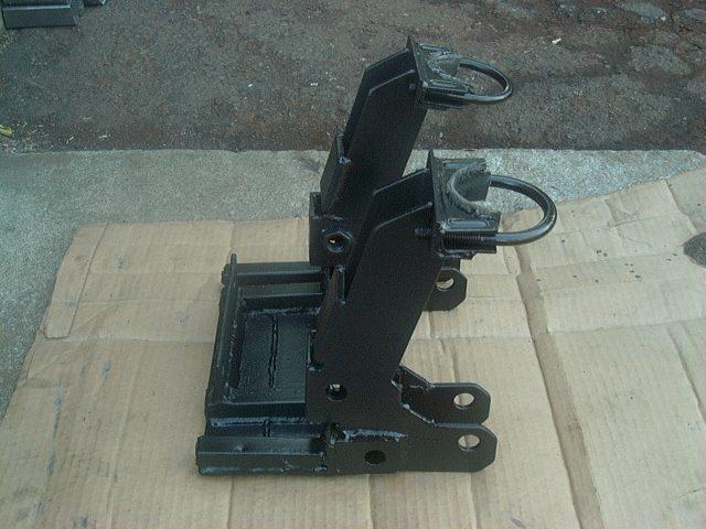 |
| Front View | Side View |
As you can see above, the new tower is all one piece and it wraps around under the frame (provides an enlarged bump stop pad) both bolts through the frame (two bolt holes in the center) and to the outside face of the frame (two bolt holes inside each tower). Now the auxiliary shocks are held in-line with the main shock which eliminates any side loading. Also with the massive side brackets on each tower, there is no flexing or give as the shocks cycle up and down. And there is little leverage on the frame, so no additional frame bracing is required as would be common with a single tall shock tower.
One modification that also has been working very well over the years is switching the top shock mount rod to a 3/4" high strength alloy steel and also adding steel tubes for inter-shock bushing spacers with compression bolts on the end have allowed the upper shock mounts to be nice and snug as well. This eliminated any slop in the bushings and the alloy steel rod and spacers have not bent in the slightest in many years of hard use.
Latest upgrade has been to swap out the 10+ year old Rancho 9012s for a set of the new 9012XL gas charged shocks from Rancho. Much softer ride and still fully adjustable. The shock body is somewhat larger than the old 9012s, but it fits fine in between the two 9120s. One side effect of the gas chaged shock is that the gas pressure forces the two side shocks to fully extend at rest instead of the normal fully retracted position.I think this works quite well, as I now have nearly 4" of uptravel on the new 9012XL shock that is nice and smooth, where before I only had less than an inch before the 9012 shock fully compressed then extended the dual 9120s, which were of course twice the stiffness of the single 9012. So as a result, the middle shock travel is used from the bumpstop down the first 12" of travel, then the side shocks start to compress for any remaining travel, where before it was the side shocks for the first 4" and the middle shock for the rest.
Lower Shock Mounts:

Here's a closeup of the lower mount, which I welded to the flipped u-bolt plate. This allowed me to position it 2" behind the axle center. If I had not moved the axle forward, I could have used the stock shock mounting bracket. In order to gain some additional clearance at the front of the springs, I had to also drop the front spring hangers 2.5" and also I moved them 0.75" forward, resulting in an overall 2.75" forward front axle location from stock:
So, how does this setup work? In a word, FANTASTIC!
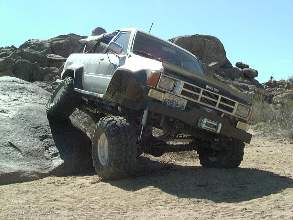

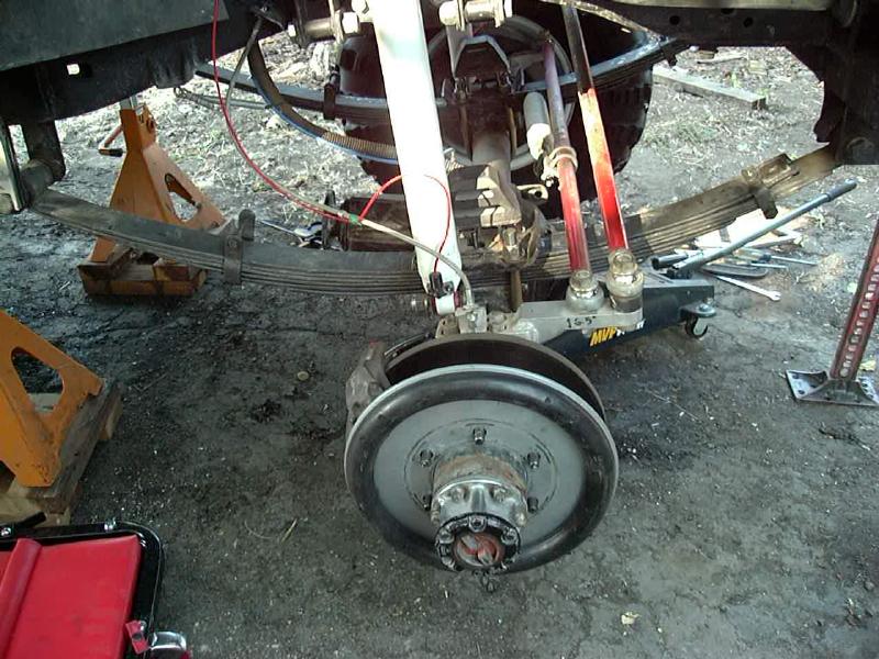
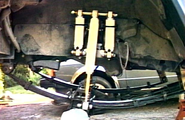
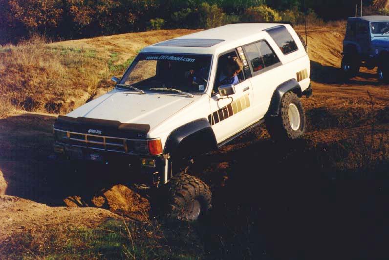
Articulation is the key, one side of the axle goes up, the other side goes down. On the left, I've backed up a boulder to twist up the front end. In the middle shot, you can see the main shock has bottomed out, and the auxiliary shocks have lifted about 2". I was running a spacer under my bumpstop in the photo, but since the clearance looks good, I'll be removing it for more up-travel. In the shot on the right, the auxiliary shocks are fully compressed and the main shock is extending. I think I measured around 24" of articulation at the rim in this shot. Once the main shock bottoms out, the auxiliary shocks lift, providing an additional 4.5" of up-travel. In effect it is like having a very tall shock tower, but without the leverage and stresses that a very tall shock mount can cause.
Since I was no longer using the stock shock mounts (or sway bar or torque rod), I decided to cut off all that excess steel while I had the axle torn down. The passenger shock mount had already torn itself off. Cutting wheels and a air hammer with cutting chisel took off the bulk of the bracketry and an electric grinder smoothed off the remainder.
Here's a look at my bolt-on lower shock mount. I serves a few functions beyond the attachment point for the auxiliary shocks. Firstly, it widens the bump stop pad on the frame to give a bigger target for the bump stop to hit, since my axle is relocated. Also, the 7/16" bolts that attach it to the frame made for handy frame ground studs for my dual battery setup. Its fabricated from a pieces of 2x2-1/8" angle and some 2x1/8" flat bar with some sections of 3/4" square tubing for stiffening. Making this bracket a bolt-on gave me two free bonuses:
- Rear bolts served as excellent frame ground studs for my dual-battery setup
- The forward bolts made perfect motor mount restraining strap attachment points
Here's a closeup of the auxiliary shock saddle clamp. I found a 2-1/4" muffler clamp was a perfect fit for the Rancho shock tubes. The two clamps are welded to a piece of 1x1-1/8" angle and two tabs below allow the assembly to be bolted to the cut off stock shock tower. I used some rubber sheeting to isolate the shock tube from the metal of the clamp. The purpose of this component is to keep the auxiliary shocks from "flopping" around and also to "aim" them out enough to allow full up-travel under the fender.
Here's the finished product in compression. Gotta love that clearance at the rear fender, now have room for 35's no problem. I did have to install longer s/s brake lines and get my drive shaft slip yoke modified for extra travel and I also had to fabricate some 2" longer spring shackles to handle the extra length. The entire project was done as a bolt-on, only had to cut off the top of the factory shock mount. If interested, I can custom build all the shock mounts for this setup, including a front u-bolt flip kit so you can bolt up the same setup. You'll need a solid front axle with crossover steering to do this
One important thing to remember if you do this sort of shock setup is that once you remove your shocks as suspension limiting devices, you better be sure the rest of the system is up to the increased travel. In my case, the s/s brake lines were too short, I had to get longer ones and I had to relocate the end of the hardlines down onto the side of the frame. Also, the travel of the front drive shaft slip yoke was inadequate and I needed to have a long travel unit fabricated.
Wide Body Shackle:
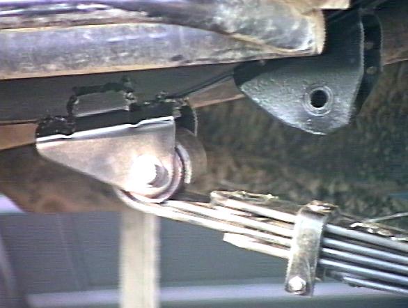
One other limitation of the stock Toyota front suspension is the way the rear shackle mount it let into the frame. Since the frame tubes are angled inwards at approx. 12° at the very location the rear shackle mount is located, there is a tube inserted through the frame to support the shackle. For clearance, the tube is approx. 1.5" wider than the eye of the spring, so in the stock design, the shackle sides are bent inwards to make up this difference. This can lead to problems in that if the shackle folds back too far, it can make contact with the frame, causing the suspension to bind up. I had this problem with the stock shackle and my NWOR 3.5" lift springs, then I used a longer Downey Rubicon (3" longer, cut down to 1.5" longer) shackle to fix that. But with the 2" longer pickup springs, this problem had returned. I contemplated getting another set of Downey shackles, but decided there must be an easier way. Another option I've seen used it to place a spring hanger below the frame, similar to the way the rear springs are mounted. This is popular with the solid-axle-swap folks, since they have no stock mount and this is easier to install than stock.
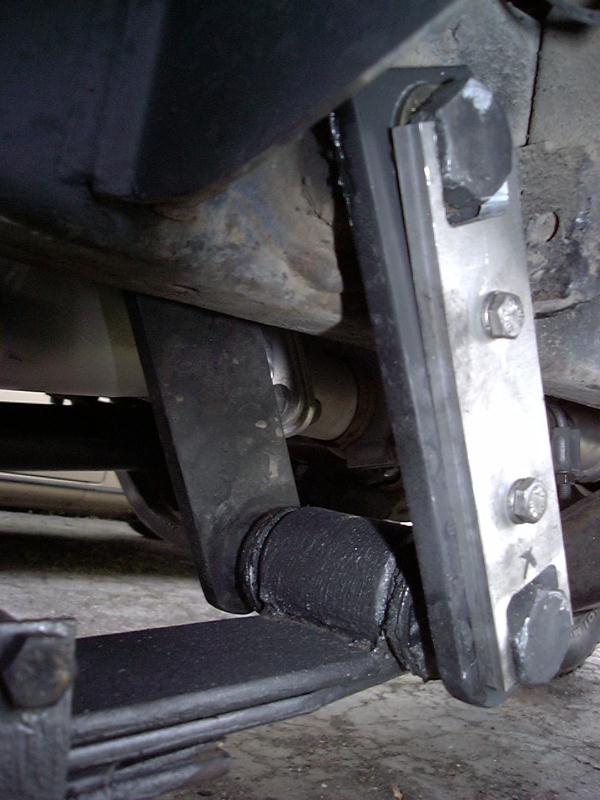
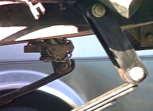
So, instead of the complex bent shackle, I adopted the "wide body" shackle design I had seen used elsewhere for use on my truck. I measured the width of the upper and lower ends of the shackle, divided the difference between the two in half and found that to be approx. 3/4". I found some black steel pipe fittings that were about that same size, reamed them to fit over my 18mm spring pivot bolts, TIG welded them to some 3/8 x 2" steel flat bar, and then TIG welded a large flat washer to the bushing to provide a flat surface for the spring bushing to slide on. The flat bar was cut 2" over stock length (i.e. 5.5" center-center vs. 3.5" stock). Then, to prevent the spring bolts from pivoting in the shackle plates (avoiding metal-on-metal wear) I fashioned some aluminum clamps to prevent the bolt heads from turning, yet still allowing them to be removed for service. I may ultimately drill them for grease fittings. Anyway, I've been happy with this shackle. The longer shackle mounted within the frame is very strong and I get the added droop the longer shackle allows without the added height a lowered shackle mount would give me.
I later replaced the +2" shackles for +3.5" longer than stock (7" center to center). This was done for a few reasons, one was to get back some positive caster angle after installing the 2.5" front spring hanger drop. A second reason was to add a brace to the shackles for a bit more stability with the added length. The combination of shackle 1" longer than the spring hanger drop and the brace gave me rock solid steering. Interestingly, I got no added ride height with the 1.5" shackle length change. If interested in making your own shackles, I also offer steel shackle spacers (essentially 0.700" thick washers) that can be used to space out the lower ends of the shackle plates at the spring eye to allow a straight sided shackle to be used.
Bumpstops:
With all the work done to the front suspension, including flipping the spring plates and u-bolts, moving the axle forward, etc. the stock bumpstops would not be useable. My shock bracket was designed in part to extend the factory bump stop plate on the bottom of the frame to at least allow a chance of a bump stop on the axle to hit it. It is both longer and wider than stock.
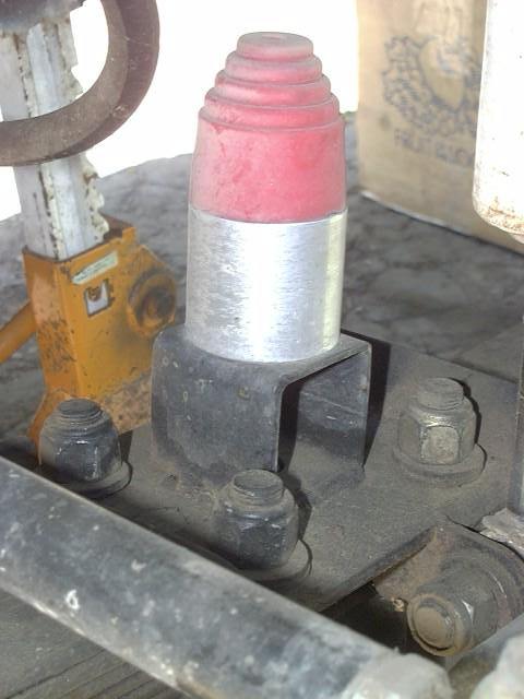
To mount the bump stops, I welded a piece of 2x2 square tubing to the middle of the spring plate. A 3/4" hole was drilled in the bottom for the center bolt and a 3/8" hole in the top for a bolt to be used to attach the bump stop. I used to use a hollow rectangular bumpstop but found it too bulky and soft. So, I switched to a 2" OD solid round polyurethane bumpstop. To allow for adjustability, I machined a 2" round aluminum spacer with the center drilled and tapped to accept the stud from the bumpstop and the bolt from the mounting bracket below. By changing out the spacers, I can fine tune the compression point to keep parts from hitting and still allow for maximum spring travel.
[Return to the top]Rear:
So, now that the front end was working to my satisfaction (ha!) it was time to look to the rear end. It was interesting running the the Rubicon with awesome front axle articulation and non-existent rear axle travel. The relatively stiff rear end would force the front axle to its limits over obstacles. With the front limited slip differential, it actually was beneficial in some respects as the front tires were forced into contact with the ground. However, this was only a temporary situation.
Long Travel Rear Shocks:
Toyota pickups up through 1983, used to run their rear shocks angled in towards the center of the frame. However, in 1984, they changed the shocks to run forward on the driver's side and back on the passenger side. They also changed the orientation of the shock mounting bolts to be parallel to the axle instead of perpendicular to it. Both these changes severly limit the ability of the shocks to handle extreme articulation off-road, both due to the relatively short length of shock that can fit the stock mounting points and the fact that the shock eye bushings bind up on the mounting bolts. I wanted to fix both these problems at the same time, so I designed a shock mount that placed the bolts perpendicular to the axle which allows the bushings to pivot on the bolt instead of bind up, and also incorporated an angle shock mounting scheme to allow a longer bodied shock to be installed.
~~~
Shock Mounting Angle examined:
One benefit of angling the shocks inward is that this allows for increased vertical travel for a given length of shock. If a shock is mounted vertically, it needs 1" of travel for each inch of wheel travel. But angled inwards, at say 45°, the shock travel is reduced by 30-40% over a vertical setup. With the 14" travel shocks I selected, I am able to achieve over 19" of vertical wheel travel (assuming my springs would allow that). A drawback to this arrangement is that the effectiveness of the shocks is reduced by the same amount the travel is increased. Since I chose an adjustable shock, I can compensate for this by "cranking up" the rear shocks for added stiffness if needed, more on this below...
When mounting a shock absorber at an angle other than vertical, several things occur simultaneously that affect the shock's damping properties. The first effect is due to the static angle. When a shock is vertical, you get 100% of the shock's damping action acting to control the suspenion's up-down movement. When you start tipping the shock over at an angle, the vertical damping effectiveness falls off in relation to the sine of the angle the shock is angled at (assuming 90 degrees is a vertical orientation). Looking at some common angles and their sine, we see:
- sin(90) = 1.00
- sin(75) = 0.97
- sin(60) = 0.87
- sin(45) = 0.71
So, what the above numbers tell you is that if you angle the shocks in at say 45 degrees, they are only 71% as effective in damping vertical motion as they were if mounted vertically. That is, if the shock generated 100 lbs. of damping force at a given velocity, only 71 of those pounds would be directed upward to resist the suspension motion. An equal amount would be directed horizontally (i.e. pushing against the frame sideways) and that force would not do anything productive. This is a static factor affecting the shock absorber effectiveness. Note that this would also apply to say a coil spring mounted at an angle as well. The more it is angled over, the less force it can apply vertically.
However, that is not the whole story. When you mount the shock at an angle, it changes length at a slower speed, for a given vertical motion, than if a shock is mounted vertically. If you look at the extremes, at 90 degrees there is a 1:1 relationship of the suspension moving up and down and the shock compressing/extending. If you were to lay the shock on it's side (i.e. 0 degrees), the shock would not move in and out at all as the suspension moved up and down. Once again, the relationship of the shock's velocity relative to the suspension's up-down velocity is related to the same sine function as above. When the shock is vertical (90 degrees), the ratio is 1.00, when the shock is at 45 degrees, the velocity is approx. 71% that of the suspenion's vertical speed.
- sin(90) = 1.00
- sin(75) = 0.97
- sin(60) = 0.87
- sin(45) = 0.71
- Note:
-
You can see this visually on the following web page:
- -> //www.saltire.com/applets/triangles/tri2sia.htm
- If you set the sides of the triangle to 10.0 units each and the angle BAC to 90 degrees, this will represent the length of the shock (on the diagonal) at 45 degrees (it'll be upside down as shown). Then "nudge" the AB distance by setting it to 10.1 units (a 0.10 unit change in length) and notice the "shock" length changes from 14.14 to 14.21 units, or a change of 0.07 units or 0.7 times the rate of change of the vertical dimension.
- -> //www.saltire.com/applets/triangles/tri2sia.htm
So what does velocity have to do with anything? Well, a shock absorber, assuming a common hydraulic design as is commonly used in vehicles today, is a device that generates a damping force that is proportional to it's speed or velocity. Ignoring friction effects (like the seals inside the shock) and spring effects (such as from internal gas pressure) and variable damping rates (as from progressive shocks), if you compress a shock twice as fast, it generates twice the damping force. Likewise, compress (or extend) it half as fast and it generates half the force. OK, so where does this take us?
With the shock at an angle, it moves slower, relative to the suspension's up-down motion, and the more it is angled over, the slower it moves. Thus, if the shock compresses or extends slower, it is creating less damping force for a given suspension speed. So this is a dynamic factor affecting shock absorber performance.
Going back to the first part of this discussion, you need to combine the static and dynamic effects of the shock's mounting angle to estimate the overall effectivenss. Since both effects are independent, their combined effect can be calculated by multiplying the factors, which in effect squares the values in the above table
- sin(90)^2 = 1.00
- sin(75)^2 = 0.93
- sin(60)^2 = 0.75
- sin(45)^2 = 0.50
So we can see from the above table, that the shock effectiveness falls off much faster than could be accounted for strictly by the static effects of the mounting angle. And if you look at going from say 45 degrees (0.50) to 60 degrees (0.75) the shocks would feel 50% stiffer at 60 degrees vs. at 45 degrees (0.75/0.50 = 1.50). And going from 90 degrees to 45 degrees, the shocks would feel 1/2 as stiff. The above is a long-winded way of saying that as the angle of the shock decreases, it pushes less hard less efficiently in the vertical direction.
So, what is the take away from all this? Mount the shocks as close to vertical as possible for maximum damping effectiveness. However, you need to temper that requirement with physically fitting a given shock into a given space. Afterall, the axle is only so wide and that limits how far apart the shocks can be placed. You only have a given amount of vertical space between the axle and the frame (or upper shock mount) so that affects how much vertical separation you have between mounting points. If the vehicle is being set up for off-road use, you probably don't want to have the shocks hanging down below the axle (rock anchors). And, unless you are planning to cut holes in the bed and run the shocks up through the floor (in which case you have unlimited room and can do whatever you want, shock length-wise), there is not a lot to do to increase this vertical separation.
So why not just use a short enough shock to fit in the space given? Shock travel is usually the answer. You want to have a shock that can extend far enough to not limit the suspenion's travel off-road. Afterall, you probably just laid out a bunch of money and/or time putting on the flexiest springs you could afford, so why have the shocks limit what those springs can do? OK, so put in a longer shock. Well, if the shock is too long, it can limit the compression of the suspension (not to mention damage the shock), so that is no good either. To get more travel out of a shock, it needs to have a longer rod. In order to allow the longer rod to fit into the shock body, the body itself needs to be longer as well. This is a dirty little secret of shocks, that in order to get 1" more travel, the shock's compressed length also increases by 1", and this is on top of approx. 5" of non-useable compressed length in a typical shock. So a 5" travel shock is about 10" long (compressed) and a 10" travel shock is about 15" long (compressed) and so on.
If you only have so many inches of vertical space to mount the shock and you need a certain amount of vertical shock travel to accomodate the suspension articulation, you have to work the numbers to find out what works. If you can find a shock that is short enough to fit the space and that also has the required travel, you are golden. Put them in vertically and call it good. However, if you have a relatively low lift that flexes quite well, you may find that in order to get the shock travel you need, the shock's compressed length is too long to fit. So this is when you resort to angling the top of the shock away from vertical. How far to go? Ideally, find the angle that is just enough to allow the shock body to fit with the suspension fully compressed (this way the suspension bottoms out before the shock does). Then make sure the fully extended shock is long enough to allow for full suspension doorp/articulation. Luckily this part usually "just works out", because as the shock is angled over, the effective extension length is increased since the diagonal distance increases less than the vertical length does. So, what you lose in damping, you make up for in length.
~~~
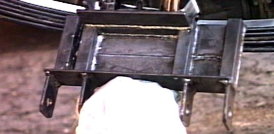
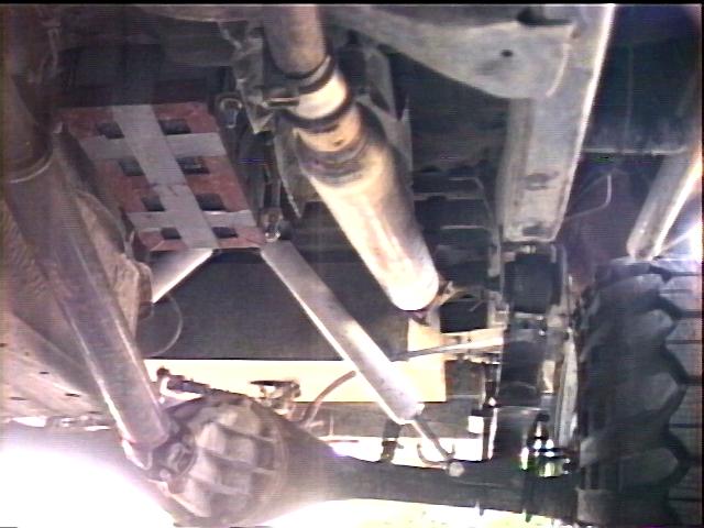
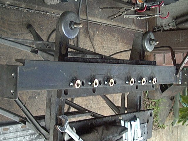
OK, back to the shocks, in back, custom shock mounts allow long travel Rancho 9012 to fit without limiting up or down travel. A u-bolt flip and custom lower shock mounts eliminate welding the mounts to the axle. Above, a shock mount on the round cross member allows room for the longer body shocks plus angles them over for increased travel. The mount is a 14" length of 2.5x2.5x1/4" angle with a piece of 2x1/4" flat bar welded (to form a "U") that wraps around the round crossmember. A pair of 5/8" bolts welded to the angle function as shock pins and a pair of 7/16" bolts go through the angle and round tube to hold it all in place. I sized and shimmed the bolts so that the nut just bottoms out on the threaded portion of the bolt, so as not to crush the round crossmember.
So, while the design may seem like a bit of a kludge, it was carefully thought out. I bolted it to the crossmember because it is darn tight up there and this way it is easily removed if I want to modify it. The bolts actually don't do a whole heck of a lot. Since they are vertical, they only serve to resist the torque applied to the mount from the shocks mounted out from the center. Also, vertical is about the only direction you can drill a hole up there without dropping the gas tank.The bracket contacts the top and bottom of the crossmember tube and helps distribute the shock load over the full 14" length of the bracket. I ultimately welded the bracket to the round crossmember. It loosened up a bit and was causing some noise. Once I settled on the final shock stud locations, I welded on another 1/2" threaded stud for a future limiting strap attachment then bolted and welded the bracket into its final location.
- Notes:
-
I had to move my muffler over a few inches to clear the left rear shock
- I also had to cut the center stock muffler hanger off to allow the bracket to fit. If you want to retain this bracket, either offset the bracket or shorten it about an inch
- The red box in the picture above is my dual battery tray
- See image below for a picture (linked to 3D VRML model of the bracket):
- I also had to cut the center stock muffler hanger off to allow the bracket to fit. If you want to retain this bracket, either offset the bracket or shorten it about an inch
Upper Bracket --- Lower Bracket
I fabricated the lower mount out of a piece of 3/8x2" flat bar and welded some 3/16x1.5" flat bar underneath for the double shear shock mount. The 3/8" bar is drilled for the spring center bolt and sits on the bottom of the spring pack. I may ultimately weld this bar to the spring perch. The bolts are aligned perpendicular to the axle to allow maximum articulation. The shock mounting position is about at the axle centerline, high enough to be out of harm's way, but low enough to accommodate the long 9012 shock body. I'll be installing 4-1/2" tall bumpstops directly to the frame rail to limit compression to this length.

Above is a shot of the lower end of the shock and also visible is the 1" spacer I installed on the e-brake cable attachment point to allow more down travel. It's just a 1" piece of 3/4" aluminum tubing and a longer bolt.
Update:
While the above setup worked OK for about 3 years, one day I noticed that the round crossmember had cracked and bent. I guess the thinwall tube was just not up to the prolonged load from the shocks and fatigued. So I cut out the center section with my upper mounts, straightened out the remainder of the tube (since it supports the gas tank and muffler on each end) and went about making a better upper mount. I had a few goals in mind, one was to have the crossmember bolt in place, so I could remove and modify it if needed. Secondly, I wanted multiple upper shock mount locations to allow for fine tuning the shock angles and thridly, I wanted to be able to run dual shocks in back. Finally I wanted to place the top of the shocks as high as possible to take full advantage of my body lift.
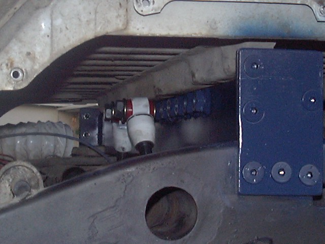
So I used a length of 3" channel cut and notched to span the space above the frame rails. I found that at the angle the shocks were at, that a 3.5" center-center spacing was the closest you could place the shocks and not have them hit each other. So, I divided that number in half and placed a series of 6 mounts along each half of the crossmemver, spaced at 1.75" centers. The two center mounts are 3.5" apart. The mounts themselves are 5/8" grade 8 nuts welded to the face of the crossmember which has a 5/8" hole drilled and tapped for the bolts as well. End places are welded to the ends and then a mounting bracket uses 3 bolts to attach the plate to the frame and the flate to the crossmember. With the 3 flat head allen bolts countersunk into the plate and screwed into 3/8" holes tapped into the frame, the fit is very snug, no play at all and very solid. Plus it comes out in about 5 minutes.
I currently have the rear shocks angled in about 29 degrees from vertical and is seems to be working fine. This is all temporary until I get the rear axle swapped out, new springs and shackles installed and then I'll make the final setup w/ dual shocks.
Now with the new rear axle in, I was able to weld some new lower shock mounts on to the axle to allow for a slightly longer shock to fit in there. I was able to fit a 34" Rancho 9000XL remote reservoir shock in place of the old 10+ year olr 9012s:
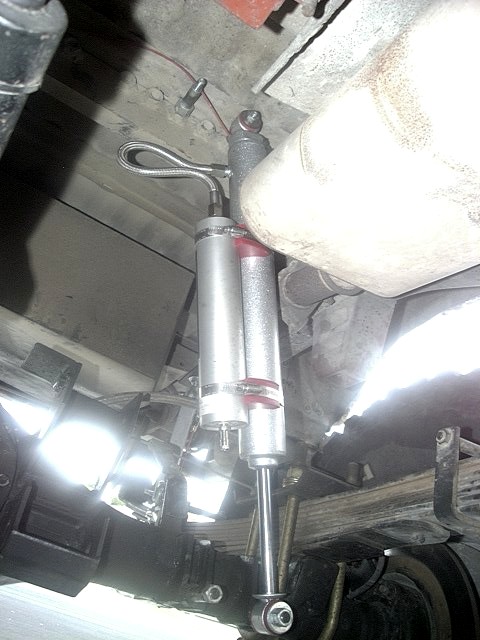
I also pushed the top shock mount all the way to the outer most upper mounting bolt hole and this gives a much more vertical shock position. The above photo was taken at one hole in towards the center. These shocks still have the air operated remote damping adjustment as the old 9012s, so that is why I went with them. Ride is much smoother with the newer shock technology.
BTW: The new rear axle is basically a wider IFS rear axle (3" wider than stock), that has been shaved, has had shock mounts and sway bar brackets welded on, with a Front Range full floater axle kit installed inside with the Supra rear disc brake caliper (integral parking brake). Finally it has provisions for a rear traction bar integrated in with a center support for a future center air bag for helping with carrying heavy camping gear. More on that as it develops.
Longer Rear Springs:
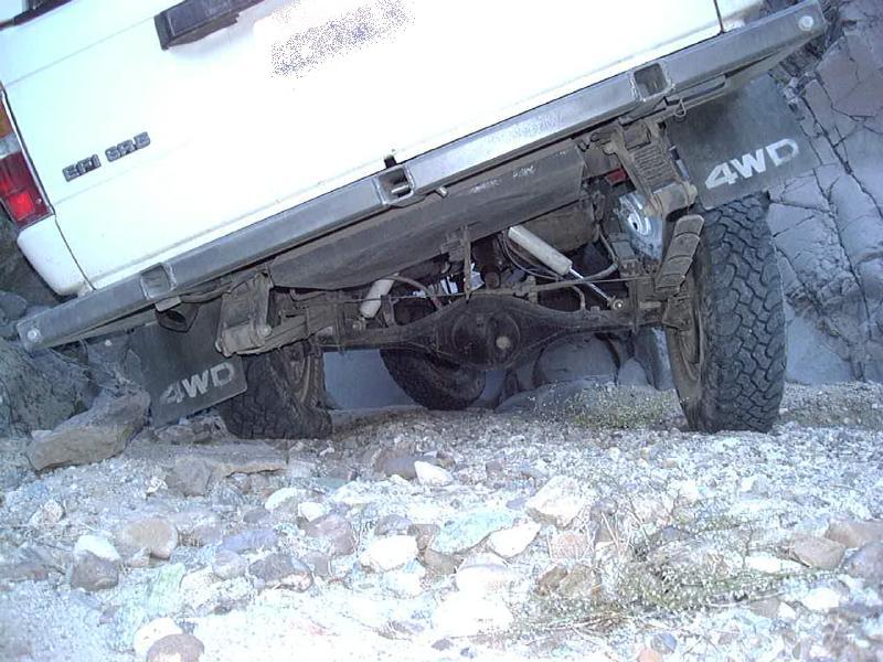
One of the main limitations of the stock springs on my 4Runner was there length, 47". With a short spring, the only way to get lift is lots of arch. Doing that makes the spring very stiff. One solution is to run a longer spring which is much softer for the same amount of arch and lift. Ultimately, I installed some custom 56" Alcan springs to replace the stock 47" long ones to really make full use of the shock travel I now have, which should be about 17" vertical. Below, is a shot of the rear with the Alcan springs installed:
To mount the Alcan springs, I ordered new rear spring hangers from
Toyota. Since the Alcans require moving the front hanger forward about
6.5", placing them lower on the frame, I opted for the later model
'91 pickup hanger. Unlike the earlier model hanger, the '91 design is
longer and tapered in front. This should help make a smoother
transition for climbing over obstacles and the extra length should make
for a stronger mount. The Toyota p/n for the '91 mounts are: 48414-35120
and 48415-35050 (for the left and right brackets).
I ordered the '89 and later Alcan spring design, which means the rear part of the spring is 4" longer than stock. This is in addition to the 5" longer front half. This results in a spring with approx. 27" from the front hanger to the center pin and 29" from the center pin to the shackle. Springs were ordered for a 6" total lift, including 2" due to the lowered spring hanger position. I ordered the springs directly from Alcan, it took approx. 2 weeks for them to be built-to-order and another week to arrive via UPS:
Alcan Spring, Inc.The springs arrived about 3 weeks after ordering them; cost $400 plus $55 shipping (ca. 2000 pricing). So, with springs in hand, I preceded to figure out where to mount them. In picture (1) below, you can see the old NWOR 3-1/2" lift spring and the new Alcan 4" lift spring side by side. The center bolts are lined up and the forward bushings are to the right. NWOR uses 4 flatter, thicker leaves, while Alcan uses 8 longer thinner leaves (plus an anti-wrap half-leaf on top).
Where to put the spring hanger?
On paper, I determined that the stock axle location would be achieved my moving the front hanger 6.5" forward. How did I determine that? Simple, I used the front half length of the old springs (20.5") and the front half length of the new srings (27") and took the difference. THis ensures that when you move the center of the new spring hanger that much farther forward than the existing hanger center, then when the springs are fully compressed (i.e. flat) the axle (and wheels) will be in the same location with respect to the body as they were before (i.e. centered in the wheel well). However, I decided to give it a try at 5.5", so I bolted one hanger there, hung a spring on it and found the rear was way to far back.
1.  |
2.  |
3.  |
4.  |
56" Alcan Spring Installation
So, I re-attached the hanger at 6.5" (picture 2 and 3) and found that with a 7" shackle (picture 4), I could get a nearly ideal 45 degree shackle angle in compression and perfectly vertical in droop. With the length of the shackle, I decided to weld a center brace in place. I used a scrap piece of 2x4 tubing.
Note: All the welding on this project was done using 7018 welding rod and 3-12V batteries in series. I used my dual batteries, isolated from the truck via my quick disconnects and then my old pickup battery. For welding on the frame, I used 3/32" rod with good results. For the heavier (1/4 and 3/8") steel on the shackles, I used 1/8" rod. While this worked OK, I found it harder to keep the arc going, I suspect the battery voltage gets pulled down too much by the higher current. I've also had good luck w/ 6011 and 6013 rod, also in the 5/32" size. This is now a permanent part of my trail repair kit.
So, that settled, I welded the driver's side shackle in place. Then, I laid a few beads of welding rod along the rear shackle mount to beef it up a bit. I'll probably also tack on an extra piece of steel along the frame rail for added support.
The passenger side requires dropping the gas tank to properly access the inner frame rail for welding the hanger on. I had dreaded this task, but in preparation had run the tank nearly empty. I pulled the skid plate, drained out the remaining fuel, then loosened the 6 bolts holding it in place. Then, through the access hole under the rear seat, remove the filler and vent tubes, and the screws that hold the fuel pump in the tank and pull it up a bit. Don't forget to separate the fuel sender connector at the back of the tank. Now, run a floor jack with a piece of plywood on it under the tank, remove the bolts and slowly lower it, working the fuel pump free as you go. Now, get the tank as far away from the truck as possible and weld up the spring hanger, let it cool, clean and paint it good. Getting the fuel tank back in was very easy as well.
Ever since I shortened my rear drive shaft after the dual transfer case install, I've experienced drive shaft vibration to some degree. After repeated balancing and alignments, I've come to the conclusion that the angle is too steep (at about 10° currently, more w/ the Alcans) for a single cardan shaft. Therefore, I've decided to switch over to a double cardan (or CV) style rear shaft. In this design, a CV joint is attached to the transfer case output flange and a traditional u-joint is attached to the rear axle pinion flange, similar to the front drive line. With a CV-style drive shaft, you need to tip the pinion up to point directly at the transfer case. A longer spring shackle helps here, but I still needed some extra shims (6-8 degrees) to get the desired angle. One benefit of a CV-style drive line, is that it tips the pinion and drive shaft up higher for better ground clearance.
One problem with the Alcan pack is that it is THICK, approx 2-3/8". That thickness, coupled with a thick 5° shim, and my 3/8" thick lower shock mount plate, the e-brake cables won't clear the top of the spring. So, I fabricated a 1-1/2" extension for the brake actuators out of some 16ga. sheet metal. I bent it around a file to make a U shape and drilled 5/16" holes to bolt to the existing arm and to attach the cable to. This gives me the additional clearance I need plus additional travel in the e-brake handle to allow finer control and more leverage. If your run into this same issus, you can order a set of e-brake extensions here.
A longer rear brake line is also required to handle the extra droop offered by the Alcan springs. I went with a 6" lift line and also modified the upper and lower brackets to point at each other to avoid putting excessive bends in the s/s brake line.
I finally got everything bolted back together. Overall, I ended up with 3 additional inches of lift, it now measures 41" from the ground to the center of the rear fender well. SInce 2" of this lift was due to the lowered spring mounts, the springs only have 1" of additional lift compared to my NWOR springs. They ride fairly flat and are *so* soft. I've still not decided if I'll stay with the single long shackle, or go to a two link arrangement or a 3/4 elliptical setup.
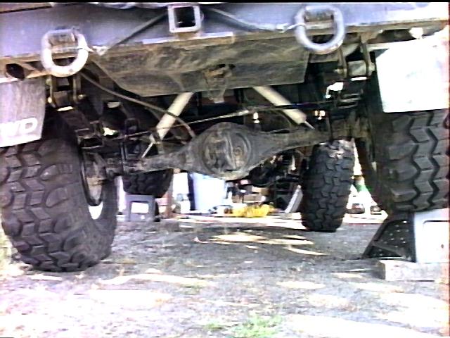
Finally got a chance to wheel with these springs, 33 miles on the Dusy/Ershim trail. One word describes them: WOW!. They really soak up the rocks and are nice and soft. I need to run the Rancho shocks on 5 to keep the body rocking to a minimum. I find I'm getting 13" vertical travel measured at the bumpstops. This should equate to 24" at the outside of the rim. The 7" long shackle is vertical at full droop and kicked back about 50-60 degrees at full compression. I'm planning to relocate the hole in the spring hanger forward about 1/2 to 1" to center the tire in the wheel well. Based upon that, I would recommend actually placing the spring hanger 7 to 7.5" forward of the stock location. The springs flex backwards nicely, even through brand new.
Here's a shot of the new suspension crossed up at Hollister Hills. I measured approx. 42" of articulation in this spot, 22" front and 20" rear. Interesting thing with all than flex is that I was able to drive through this ditch in 2WD (rear Detroit locker - I was suffering from a cracked Birfield joint at the time) with no difficulty. Once again, my rear shocks have at least 4" of extra travel in their present configuration so I've got some room for future expansion :)
Plans call for some ~59" AOR Orbit Eye springs, 5.5" lift, relocated shackle hanger and new wider front spring hanger, set into the frame and gusseted to make a smooth transition from frame to hanger. The stock Toyota hangers have proven to be my lowest hanging bit that likes to snag passing rocks.
[Return to the top]Orbit Eye spring swap:
While the 4" lift Alcan rear springs were working great, I did finally decide to replace them. Over the years, my front end had gotten taller as I got it all worked out. Dropped spring hanger and longer spring shackles plus adding some leaves to support the load up front all pushed the front higher. Since it was working so well, I did not want to mess with it. Also, it seemed that the spring bushings and spring twist was severely limiting the rear axle articulation. Seemed like the springs "wanted" to flex more, but they were just binding up and were not able to do so. So, to solve both problems, I opted to replace the 4" springs with some 5.5" springs and have the spring eyes upgraded to the Orbit Eye spherical joints. I think I am really only getting about 3"-4" of lift out of the 5.5" springs.
[Return to the top]Double Spring Shackle:
[Return to the top]U-Bolt Flip:
In the stock configuration, the Toyota mini-trucks have a squared-off u-bolt the wraps up and over the spring pack, with a plate and retaining nuts located below the axle. As such, the nuts and especially any exposed u-bolt threads are vulnerable to trail damage. Not to mention the precious inch of ground clearance they eat up. So, with the spring swap I also did a u-bolt flip, which involves finding a u-bolt that will wrap around under the axle and pass through a new plate that sits on top of the springs.
I had earlier installed an AllPro front u-bolt flip kit. It worked fine for about 6 months, but then I found the 1/2" diameter u-bolts seemed to be bending and stretching and the, once long, retaining nuts were crushing and deforming with repeated use. Then a few hours into the Dusy/Ershim trail, I felt some excess play up front. I tried to torque down the u-bolts but found one nut on the verge of stripping out, so luckily I had a few spare nuts and double-nutted as many of the bolt ends as I could. The upper spring plates were adequate, although I also noticed some bending in them over time. Since I had already welded on my bumpstop and shock mounts and steering stabilizer brackets to the AllPro plates, I decided to keep using them and simply find a heavier u-bolt to use in place of the originals.
In the meantime, I acquired a set of rear u-bolts and spring plates from a friend. The plates were made from 1/2" steel plate and the custom-made u-bolts were 5/8" diameter, with 15/16" (24mm) nuts. They were a joy to work with, they torqued down to 100 ft.lb. with ease, never felt like they were about to strip out and they stayed tight. So, for the fronts, I wanted the same secure feeling. I found that Rancho makes a perfect match for the Toyota axle with their p/n RS17436 U-Bolt kit (size: 5/8" x 3.25" x 8.75"). They cost about $25/pr. and are long enough to fit the long inner passenger side position, and can be trimmed for the other places. Actually, it took a bit of work to get that inner passenger bolt installed, as the bolt has to "bend" around the axle housing, due to the slight tilt in the spring perch relative to the housing. I used a 20T shop press to put a "slight" bend, perhaps 1/4", in both sides of the bolt to get it to line up. Interesting note, with the original AllPro bolts, the same "modification" must be done, and it can be done by bending the bolt over your knee. Note: If you run any angle shims up front, chances are you may not be able to fit these 5/8" u-bolts on your axle. In that case, the thinner 1/2" bolts may be a "better" solution.
Modifying the AllPro spring plates for the larger bolts, requires a bit of work, as the existing 1/2" holes must be drilled to 5/8" to accept the new bolts. However, since the inside dimension of the u-bolt is the same width, regardless of bolt diameter, the larger holes must be drilled "off-center", that is the inside edge stays the same, the outside edge gets drilled 1/8" farther out. Without a milling machine, this is difficult to do. Another option, is to re-drill the hole to 3/4", which adds 1/8" on all sides of the hole, allowing the larger bolt to fit. In any event, it is probably easier to make new plates from scratch, to fit, than to modify and existing plate.
[Return to the top]
![]()
 ===>>
===>> 
[Last updated: 09.October.2024 ]
Visitor # since 18.MAR.2002