A-Pillar Gauge Pod Installation
by: Roger Brown
Introduction:
Gauges, love 'em or hate 'em. You either have too many or you don't have enough. My 1985 Toyota 4Runner came with the SR-5 complement of analog gauges including:
- Speedometer/Odometer
- Tachometer
- Oil Pressure
- Water Temperature
- Battery Voltage
- Fuel Level
- Plus all the nifty clinometer dials and a digital clock
While people may debate the accuracy of the factory gauges, I find they are OK. They don't give you any real numeric data, but serve to indicate whether things are normal or not. One gauge I used to have in my old VW Rabbit was a vacuum gauge. I found it quite helpful to get an idea of how much reserve power I had, a handy thing to know in an underpowered 4-cyl. vehicle. For example, if you were climbing a grade on the highway and came up on slower traffic, if the vacuum was down near 0", chances are you had no extra power left to pass the slower traffic. One day, I saw an inexpensive vacuum gauge at the auto parts store and I picked it up, figuring I'd find someplace to put it later.
Shortly after that, I got an e-mail out of the blue about someone that was considering making an A-pillar gauge housing for the '80s model Toyota trucks. I checked into it, turns out I knew the guy working on this and expressed my interest in the project. A few months passed and finally the parts were ordered. More time passed and the parts were in. I picked up the housing and headed home to see how it fit.

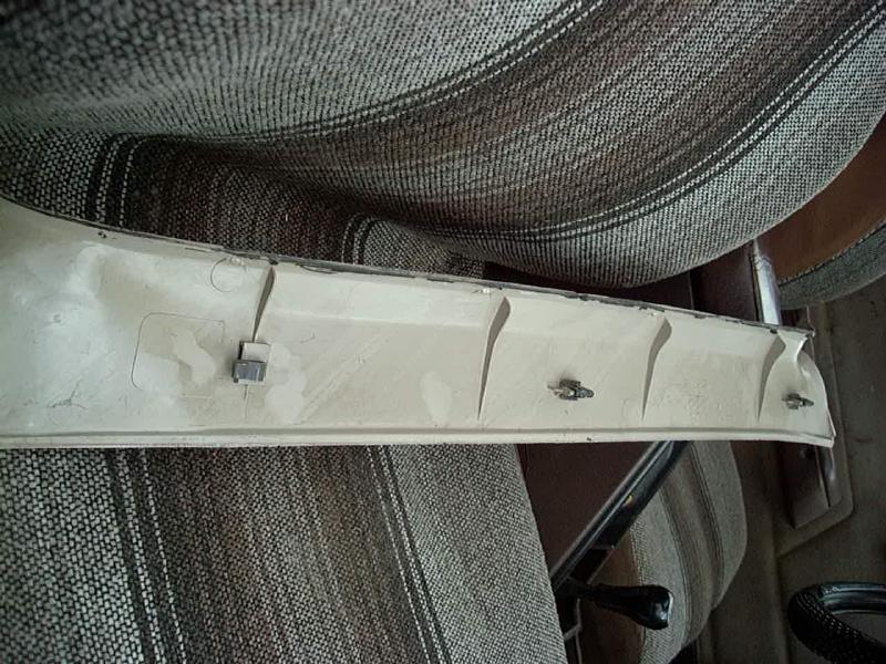
First problem I ran into was how to get the stock a-pillar trim plastic off. If you look closely at the pictures above, you can see the trim is held in place by three tabs, the upper two are pressed into holes in the pillar and will pop straight out with gentle prying with a flat blade screwdriver, but the bottom one (the leftmost tab in the above right picture) is hooked into the pillar hole and so must be lifted upwards, not outward like the rest. To complicate matters, my pillar trim was secured by a sloppy bead of windshield glue on the glass side. I had to run a razor blade down the glass a half dozen times before the trim was free. It should come off easily, don't force it.
Now, time for some gauges. I finally settled on the following set:
I chose to use Intellitronix gauges that I ordered from Summit Racing. It seems that Intellitronix brand disappeared for a while and was replaced with the Nordskog brand and now both seem to be in use. However, it seems that they have moved away from the analog format to all digital.
Vacuum Gauge:
The vacuum gauge was mounted on the bottom to and vinyl tubing run to the air intake plenum for a signal. I found one fitting at the back of the plenum with 3 ports, one of which was plugged, that I used for the connection.
Air/Fuel Ratio Gauge:
The air/fuel meter hooks into the stock O2 sensor circuit and has a buffer amplifier that isolates the gauge from the ECU in reading the O2 sensor voltage. It works fine and causes no problem with the ECU. I like the setup that way since I can watch the output of the sensor the ECU uses in order to see if everything is working OK. Some A/F guages use a separate sensor and while a wide-band sensor would give a better reading of air/fuel ratios for engine tuning, you would not directly know if the stock sensor is working properly.
Fuel/Air Pressure Gauge:
The fuel and air tank pressure gauge uses 100 psi senders. One is installed in the fuel injector rail (drilling and tapping the end of the rail to accept the sender) and the other sender was installed in place of the analog gauge in my on-board air system. The fuel injector rail was end cap was drilled and tapped for 1/8" NPT pipe thread and a 1/8" - 1/4" NPT street elbow was threaded into that hole. It was soldered in place as the end cap is fairly thin material and I was worried about sealing the fitting against fuel pressure. The solder works well, have had no problems in over 2 decades of use. The fuel pressure sender uses 1/4" pipe thread fittings and due to the size/shape, needed to be angled downward at a 90 degree angle to fit. Unfortunately I did not photograph the sender install before putting the intake back on and it is not possible to take a picture of the installed sender now. Since I was converting to ARB air lockers, I had relocated my air compressor switch to the cab and also wanted some sort of readout of the air pressure in the tank. I ran both senders to a 2PDT switch which then connected to the gauge. Before, when only used for airing up, the gauge and switch were under the hood.
Having the combined fuel and air pressure readings available has proven quite useful. I've used the fuel pressure guage to diagnose a couple of starting and running issues with the engine over the years. For example, having the engine crank and crank without starting. A quickj glance at the fuel pressure and seeing that at 0 tells me the fuel pump is not running.
The gauge housing is set up for 2" or 2-1/16" gauges (the more common size).
Keep in mind that any factory threaded fitting into the block will likely be BSP (British Standard Pipe thread) and not NPT. They are physically the same diameter but in the 1/8" pipe size, NPT is 27 threaded per inch (TPI) and BSP is 28 TPI. You'll not be able to get a leak-free seal if you try to use a sender of the wrong thread pitch. There are adapters available to allow an NPT sender to screw into a BSP threaded hole.
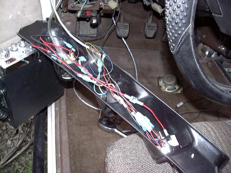
With the gauges in place, I made a wiring harness of sorts (see picture above), connecting the power, ground and light connections and signal inputs. The gauge housing attaches with two sheet metal screws (not supplied) to the sheet metal of the pillar. Space is fairly tight behind the housing, keep wire sizes to a minimum.
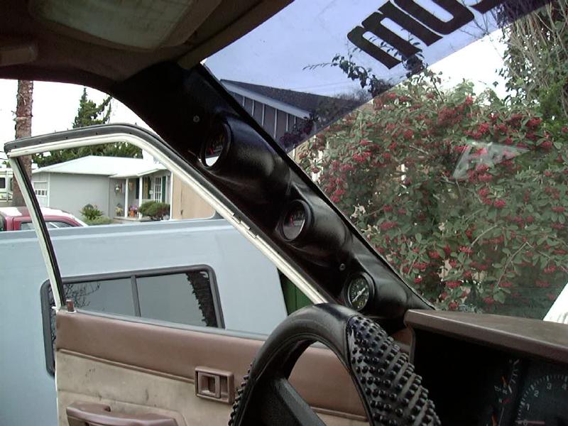
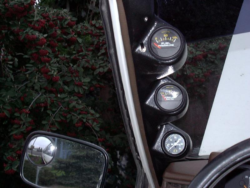
The (nearly) finished project. In the above photos, you can see the gauges. The top one is fairly close to the driver, I used it for my fuel/air pressure readout. Not something you need to look at much at all. Air/Fuel gauge in the center and the manifold vacuum is at the bottom, where its easiest to see. Vision is slight obstructed to the left, but not much more than stock.
I have surprisingly found the Air/Fuel meter to be very handy while driving, more so than the vacuum gauge. With the EFI system, the optimal engine operation is had in what is called "closed loop" mode, that is when the ECU is reading the residual oxygen level in the exhaust gas and adjusting the fuel injector timing to get an optimal air/fuel ratio (14.7:1). This mode is easy to detect on the A/F meter, as the needle "twitches" back and forth between lean and rich about once a second or so. I have found many occasions where I might have a choice of gears to run in on the road. Maybe I can have it floored in 4th gear up a grade or drop to 3rd and let it rev higher with less throttle. Conventional wisdom would say that 3rd gear would be the best, but in 4th, it'll stay in closed-loop mode, while in 3rd, it'll go to full rich. I find these sorts of situations arise at higher elevations with lots of gradual up hills, such as you find in the basin and range country in the west. When pulling a 10 mile long grade, if you can do it in closed-loop mode, it is likely saving gas over doing the same hill at full rich.
Wiring:
There's not a lot of room to get wires into the gauge housing, especially with the vacuum gauge and it's associated hose. So I ran a length of Cat5 type cable that gave me 8 wires for the bulk of the connections.
- Black - Chassis Ground
- Blue - Ignition Power
- Yellow/Green - Air Fuel Signal from the buffer amplifier
- Red/Orange - Air Pressure Sender from On-Board Air System
- Brown/Tan - Fuel Pressure Sender
Source:
The gauge housing is a semi-custom design that fellow wheeler Jeff Moskovitz had fabricated. Cost was less than $60 including shipping (1999 prices, somewhat higher now). Feel free to consult the A-pillar FAQ page at:
- http://www.well.com/user/mosk/gaugepillars.htm
- Although is seems that LC Engineering is now offering these parts.
[Last updated: 23.July.2025 ]
[Initial creation: 13.MAR.2000]