VW IDI Diesel - Glow Plug System
Contents:
[Return to the to my Diesel index page]Overview:
The VW Diesel glow plug system consists of a number of components:
- Glow Plugs
- Bus Bar
- Fusible Link
- Glow Plug Relay and socket
- Engine Temperature Sensor
- Ignition Switch
The purpose of the glow plug system is to pre-heat the combustion pre-chambers in the indirect injection engine for easier starting when the engine is cold. Once the engine is warmed up, the glow plugs are no longer needed and the system turns them off. On my '81 VW diesel, the glow plug relay is located under the dash, but it is not part of the main fuse panel.
There are two types of glow plug systems used by VW, commonly referred to as "slow-glow" and "fast or quick-glow". The parts to both systems are distinctively marked and should not be inter-mixed (see Details section, below):
- The "quick-glow" system is factory installed on all normally-aspirated diesel Jettas and '82-'84 Pickup and Rabbit models.
- The "slow-glow" system is factory installed on '81 and earlier Pickup and Rabbit models as well as all turbo-diesel (TD) engines. Its use on the TD engines is to avoid excessive smoke after a cold start that the "quick-glow" system can cause.
- This description was from a '77-'84 Bentley VW Diesel Service Manual, it seems that most, if not all, VW diesels had the fast glow system instaleld from '85 onwards.
Details:
There are two basic glow plug systems used in VW diesels, commonly referred to as Slow and Fast glow. Early engines and turbo-charged engines use the slow glow system while later, non-turbo sengines use the fast glow system.
Glühzeit-Steuergerät (in English "Glow Timer")
-
Slow Glow:
-
Plugs:
- VW p/n:
- Bosch p/n:
- Current draw: 9A/plug, silver colored terminal
-
Relay:
- VW p/n: 321-911-621
- Bosch p/n:
-
Plugs:
-
Fast Glow:
-
Plugs:
- VW p/n:
- Bosch p/n:
- Current draw: 12A/plug, brass colored terminal
-
Relay:
- VW p/n: 171-911-261A-E
- Bosch p/n: 0.281.003.099
-
Plugs:
Operation:
The glow plug relay (or timer) is a fairly simple circuit built around a quad low-power voltage comparator (LM2901), a high current relay, a couple of transistors, diodes, resistors and capacitors. The circuitry is designed to provide a couple of variable delays, after application of power via the glow and start positions on the ignition switch, based upon engine temperature, as follows:
- The first delay controls the illumination of the glow plug LED on the instrument panel, used to indicate when the glow plugs have reached starting temperature.
- The second delay is used to keep the glow plugs energized for a few seconds after the LED goes out, to provide supplemental pre-heating of the intake fuel-air mixture during starting.
- A third delay is triggered when the ignition switch is turned to the start position, turning the glow plugs (back) on during the starting cycle. I have observed some relays that do not turn off after the starting cycle is done.
A temperature sender, mounted on the cyliner head, sends a variable resistance signal to the relay as an indication of the engine temperature. This is a fairly low resistance device, a few hundred ohms when cold, with a lower resistance as the temperatures rises. One potential problem arises if the sensor, wire or connection to the relay fails open, the relay may "think" the engine is cold all the time, and potentially run the glow plugs too long, shortening their life.
The glow plugs are electrically heated devices. They typically pull a very high current (30-40A when cold, tapering off to 9-12A when hot) at 12V and will glow red hot within a few seconds of applying power. A good test of operation is to use a 10A (or larger) battery charger to power the plug temporarily. If a red glow or high current is not observed, the plug has most likely failed or burned out.
[Return to the top of this page]TroubleShooting:
There are basically two methods for testing the glow plug system, in-place and out of the vehicle. I have experienced failures in almost all the components, so its best to isolate and test each component when problems are present. First off, signs of glow plug trouble include:
- Difficulty starting, increasing with decreasing temperature
- Rough running engine when cold, with lots of white/gray smoke smelling of unburnt diesel
These symptoms are signs of other problems, too, so more testing is warranted before replacing parts.
Fusible Link:
First item to check is the fusible link on the engine side of the firewall. Follow the heavy wire from the glow plugs to the fuse housing. Pull off the cover and inspect the link. I've had a burned out link and also plain old loose screws cause starting problems. If you have to replace this part, why not go ahead and pick up a few extra, they are inexpensive and might come in handy one day.
Glow Plugs:
There are several ways to test glow plugs. The way I use when I suspect one or more are bad is to remove them (disconnect the injector plumbing between the pump and injectors) and clamp a 10A battery charger on the plug. If its not glowing red hot in the correct time (7 or 30 seconds) it gets chucked in the trash. If it does glow, I keep it, but if any plugs have failed, I usually replace all 4 and keep the working units for spares. I also clean the copper bus bar surfaces before putting everything back together.
Relay:
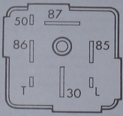
The Glow Plug relay is in a 7-pin socket undder the dash, with pinouts as follows:
| Pin | Description | Input/Output |
| T | Temp Sensor | Input |
| L | Glow Plug LED | Output |
| 30 | Battery Power | Input |
| 50 | Starter Signal | Input |
| 85 | Ground | Input |
| 86 | Pre-glow Signal | Input |
| 87 | Glow Plug Power | Output |
And the image below shows the location of the above pins in the relay module socket:
All signals can be tested at the socket, with the relay removed. One somewhat common problem is that the plastic support tabs inside the socket can break, letting the contacts they support push inside the socket when the relay is inserted. This can be easily detected when you test for signals at the socket. Use the meter probe to push on each contact and see if its loose. If so, you can use epoxy to repair the broken support and then be careful when you re-install the relay.
Test Results:
I once built a test fixture and plugged in and tested a batch of "bad" glow plug relays I had collected over the years. I found out in testing them that actually they all worked, if given decent input signals. By decent, I mean that there was good contact between the input and the relay (connections at both ends and the wiring in between) and that the signal was within a reasonable range. Most common culprit was the T (coolant temperature sender) input. My tester had a variable resistor that I could use to adjust the T input resistance with. I found that as long as that was within the range of about 100-1000 ohms, all the relays worked fine. But if I put in either a short or open circuit (0 or infinite ohms) the bad relays would all act up in one way or another. Some would stay on for an unusually long time (or never turn off), some would turn off normally but when hit with the 12 volt input from the starter (50 terminal) they would kick on. Others would randomly turn on and off for no apparent reason. And what I did find was that the Bosch brand relays I had would work normally with any sort of T input from dead short circuit to open circuit. It seems they were designed to tolerate a wide variety of input signals and "do the right thing" regardless of the input. Internally, there was a wide variation in the relay circuit board, some were all discrete components (transisitors, resistors, capacitors, etc.) and others were a single IC (integrated circuit) with a few external components. So in my vehicle, I have chosen to only use Bosch glow plug relays from now on. In fact the one I currently have in my '82 diesel has been working flawlessly for 8+ years now since I acquired the vehicle.
Oh, and as to that test fixture, I no longer have it as I had to trade it for a pair of glow plug relay socket/wiring harnesses I used to build the tester. I do have a 2nd socket but have not had time to make a 2nd tester with it. But the tester was very simple, basically the socket mounted in a smal electronics box. It has a light off the glow plug output, an LED off the LED output, a variable resistor (as mentioned above, basically an audio volume potentiometer) to feed the T input and then some switches to connected to the 86 and 50 terminals to simulate pre-glow and starting. With that, I could plug in a relay and test all the input conditions.[Return to the top of this page]
References:
Here are some other references to the VW Diesel Glow Plug System I've found on the net:
- Martin Jägersand has an excellent collection of VW/Diesel information including the glow plug system
[Return to my Diesel index]
Visitor # since 28.AUG.2003
[Date Created: 29.OCT.1999][Last updated: 03.January.2024 ]