Toyota 2.4L/3.0L Throttle Position Sensor
(22RE, 22REC, 22RET, and the 3VZx variants)

Contents:
Return to the main Cheap Tricks page...
Introduction:
If you have come here, you are either having problems with your TPS reports:
 |
What's happening? Uh... we have sort of a problem here. Yeah. You apparently didn't put one of the new cover sheets on your TPS reports. Mmmm... yeah. You see, we're putting the coversheets on all TPS reports now before they go out. Did you see the memo about this? Yeah. If you could just go ahead and make sure you do that from now on, that will be great. And uh, I'll go ahead and make sure you get another copy of that memo mmm'k? |
Fun Fact: In the movie Office Space, TPS was an acronymn for Test Program Set which is a real document that describes testing procedures for software programs.
Or your Throttle Position Sensor:
The Toyota 22R-E and 3VZ-E engines are electronically fuel injected. As such they lack a mechanical carburetor and instead split the function of the carburetor into three parts, namely the Air Flow Meter in the air cleaner box, the throttle body and the fuel injector. The air flow meter uses a flapper vane and temperature sensor to detect the temperature and velocity/flow of the incoming air charge. The throttle body controls the air flow into the engine and the fuel injectors supply the proper amount of fuel to each piston depending upon operating conditions.
While this information is based upon the TPS system in the 22R-E engine, most of it applies to other Toyota EFI engines. For specific information, be sure to consult the service manual for your model engine.
[Back to the top]
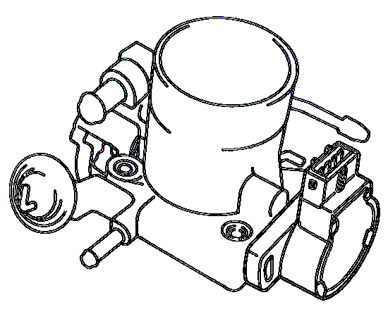
Throttle Body:
|
The throttle body (Figure 1) contains the throttle valve that it operated by the accelerator pedal in the driver's compartment. The valve serves to regulate the amount or air that gets introduced into the engine. The fuel injectors spray atomized fuel into the intake of each cylinder in response to an electrical signal from the engine computer (ECU). One determining factor (among many) for the amount of fuel to inject is based upon the position of the throttle valve. This position is determined by the throttle position sensor (TPS).
So why test it? Well, assuming you are having an engine-related issue that you think might be due to the TPS (see troubleshooting section for common symptoms), then it makes sense to test the one you have first. Why?
- Well, yours may just be adjusted improperly. A simple adjustment will not cost anything and if it fixes the problem, you are ahead of the game time- and money-wise. And with a new TPS, you'll need to adjust it properly after installing it, so if you think the test/adjust procedure is a hassle that a new TPS lets you avoid, THINK AGAIN!
- If the adjustment does not help, then at least you have eliminated that as a cause. If the TPS, after adjustment, tests out OK electrically, you may have a wiring issue between the TPS and the ECU that is causing your issue. If this is the case, then a new TPS will not solve anything and you'll be ticked you wasted the money on a new TPS (they are not CHEAP)!
- And finally, if your TPS tests out bad, then you know it is bad and when you get a new (or used) TPS to replace it, you can test it and make sure it is good before installing it. And then after you install and adjust it, you'll know that the new part was indeed the fix for your problem.
Throttle Position Sensor:
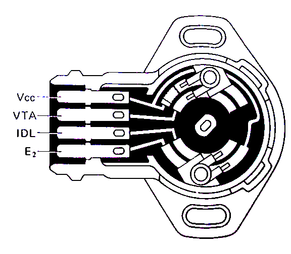 |
The Toyota 22R-E (and R-EC) engines use a "Linear" throttle position sensor. The sensor basically looks at idle or closed throttle (IDL) and throttle angle opening (VTA). The TPS itself is simply a linear variable resistor that when driven by the ECU produces a linear voltage in a 0-5 volt range, 0 volts being idle and up to 5 volts representing throttle opening angle. Internally, there is also a switch that detects the idle position.Proper adjustment of the TPS is critical for engine performance, fuel economy, and emissions. An improperly adjusted TPS effects many other inputs and outputs from the ECU, many of which would not even logically point to the TPS. Aside from being out of adjustment, the TPS can just plain wear out or break internally.
Periodically, the throttle body should be cleaned or checked for a buildup of sludge that may clog the air bypasses, vacuum ports, or prevent the throttle plate from closing to it's proper position. This should be checked prior to any adjustment of the TPS should a trouble code relating to throttle position appear during a self-diagnostic test. Crankcase vapors are commonly vented into the throttle body for re-introduction into the combustion process (by the Exhaust Gas Recirculation, or EGR, valve). These vapors can leave an oily residue on the back of the throttle pate and allow sludge and dirt to accumulate. The throttle body can easily be cleaned while on the vehicle with a little carburetor cleaner and a cloth. However, for heavy sludge buildup, it should be completely removed, washed in solvent, and dried thoroughly. When doing this, it is important that the TPS should be removed to prevent contamination (a primary cause for failure) and the throttle body-to-plenum gasket replaced.
[Back to the top]
TPS Adjustment:
The TPS is adjusted by means of rotating it slight with respect to the throttle body itself. To check the TPS, first unplug the connector from the sensor, then using a thickness gauge between the throttle stop screw and the stop lever, use an ohm meter (see Figure 3)to check the various terminal-terminal connections for proper resistance values (see Table 1). Obviously, these tests are done with the engine not running.
 |
 |
 |
 |
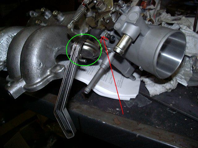
| 4: Feeler Gauge Placement | 5: Ohm meter Connection | 6: Throttle Body |
Pictured above:
- #4: Shows the throttle body (w/ TPS attached to the back side - not visible) with a feeler gauge inserted between the throttle lever and the throttle stop screw (highlighted with the RED ARROW - click on the image for a larger view - and note this is different than the spring-loaded dashpot adjustment screw).
- #5: Shows where the ohm meter probes are connected for testing the TPS.
-
#6: Shows the Throttle Body from above.
-
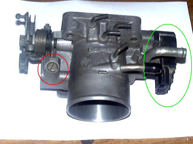
Circled in RED is the idle speed
adjustment screw
- Note that this is the screw that adjusts the normal idle speed (after the engine has warmed up).
- And further note that you DO NOT ADJUST the idle speed with either the throttle stop screw, the dashpot screw or the white plastic knob atop the A/C (or P/S) idle-up valve on the intake or with the "RPM" knob on the A/C Amplifier "black box" behind the glove box.
- Circled in GREEN is the TPS attached to the side of the throttle body.
-
Circled in RED is the idle speed
adjustment screw
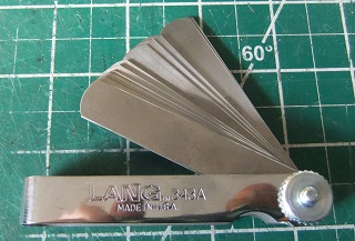
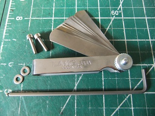
We now offer a quality metric feeler gauge set that allows all the various throttle stop gaps to be set with one or two shims in various combinations. It has 0.04-0.09mm shims in 0.01mm increments plus 0.10-1.00mm in 0.05mm increments. Cost is US$22.00 plus domestic US postage (only). Also have added a deluxe TPS screw kit with the stainless steel screws, ball-end allen key and the metric feeler gauge for US$30.00 plus domestic US postage (only). Ships in 1st class parcel. We assume customers outside the US can acquire metric feeler gauges locally.
 |
 |
| Metric Feeler Gauge w/ US shipping | Deluxe TPS Screw Kit w/ US shipping |
- Notes:
-
Dash Pot:
- The GREEN CIRCLE shows the dash pot (DP) which is there to slow the closing of the throttle to prevent backfiring. It consists of the round air bellows, a spring loaded plunger, and the air vent line that attaches to the fitting at the base of the bellows. The vent line has a check valve in-line and an air filter to keep dirt out. The check valve lets air into the bellows then the throttle opens and extends the plunger. When the throttle closes, the stop screw contacts the plunger and pushes it in. The check valve closes to slow the air escaping the bellows and thus slow the closing of the throttle.
- To troubleshoot the DP, make sure the air filter is clean and make sure the check valve is not clogged or stuck open. You should be able to blow air into the bottom easily (filling the bellows) but it should be hard to suck air out. Both the filter and valve can probably be cleaned with a mild solvent. Also, the plunger can stick. I find a shot of silicone spray applied to it periodically helps keep it moving freely. Lube it the push it in and out fully a few times to work the lubricant down into the plunger. And you can simply back the adjuster screw all the way back to keep it from contacting the throttle linkage as a test. This way it is eliminated from affecting the throttle operation, in case you think it may be causing a problem.
- To adjust the DP, I find setting the stop screw to depress the plunger about 1/2 of it's travel works well. If set too deep, you have more spring force to overcome and that can cause the throttle to not fully close. Too shallow and the DP can't really do it's job.
- Throttle Stop Screw:
- The other item that scan affect the TPS adjustment is the Throttle Stop Screw. The stop screw controls the amount of closure for the throttle plate inside the throttle body. It must be set properly BEFORE adjusting the TPS itself. How is this done? The stop screw is set so that the throttle plate is fully closed inside the throttle body, then it is turned in to contact the throttle linkage and then 1/4 turn more before tightening the jam nut to lock it in place. This is done so that the throttle plate is held just barely off fully close to prevent it from sticking inside the throttle body.
- The GREEN CIRCLE shows the dash pot (DP) which is there to slow the closing of the throttle to prevent backfiring. It consists of the round air bellows, a spring loaded plunger, and the air vent line that attaches to the fitting at the base of the bellows. The vent line has a check valve in-line and an air filter to keep dirt out. The check valve lets air into the bellows then the throttle opens and extends the plunger. When the throttle closes, the stop screw contacts the plunger and pushes it in. The check valve closes to slow the air escaping the bellows and thus slow the closing of the throttle.
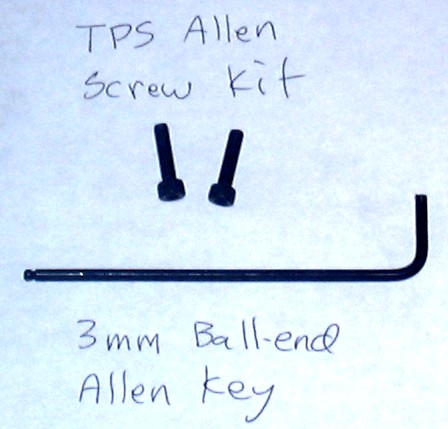
Allen Head Screw Upgrade:
The only real problem to adjusting the TPS is that the screws are nearly impossible to access when the unit is on the throttle body installed on the intake. To make adjustment easier, you can replace one or both TPS screws with allen head screws and then use a ball-end allen wrench to loosen and tighten them. Pictured below are the pair of metric allen head screws used to replace the stock Philips head screws and below that is the optional ball-ended 3mm allen key that makes removal and installation of the screws plus subsequent adjustment of the TPS easier:
 |
 |
| A: TPS Screws and ball end Allen Key | B: Screw Length Measurement |
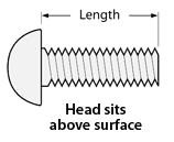
If you can't locate the extra fine pitch metric screws, they are available for purchase below. The first kit is just the two stainless steel allen head screws. This kit should fit both 22RE/REC/RET 4-cyl. engines as well as the 3VZE V-6 engine throttle position sensors. Included with the screws are two washers. In certain applications, you may find an extra washer or two may be needed in case the new screws bottom out in the threaded hole in the throttle body. The 4mm dia. screw length is 16mm, matching the longest stock screw length or also available in the shorter 12mm length. The second kit includes the screws and a long-arm ball-ended 3mm allen key which allows for off-angle access to the upper screw. The lower screw can be accessed from the side with the thermostat housing removed, or from the front using the short end of the wrench.
Typical TPS screws are approx. 5/8" (16mm) long from the base of the head to the end of the threads. This length seems to fit most applications, but certain years may use a shorter approx. 1/2" (12mm) long screw, two known years that may have this size are the 1989 and 1990/22RE. If in doubt, remove the upper screw and measure the length. Or if that is too much hassle, order the standard 16mm screws and if needed, you can always add a few washers under the longer screw if needed, as it is easier to make a screw shorter, but it is very hard to make it longer! Kit is a pair of stainless steel screws and washers with an optional ball end allen key. Ships in 1st class parcel.
| TPS Screws - US$5.00 | TPS Screw Kit w/ Allen Key - US$10.00 |
| US Delivery | US Delivery |
| ~~~~~ | ~~~~~ |
| Can/Mex Delivery | Can/Mex Delivery |
| ~~~~~ | ~~~~~ |
| Int'l Delivery | Int'l Delivery |
You'll likely need to either remove the throttle body or at least the thermostat housing on the 22RE engine to remove the old screws before installing the new allen screws. You'll likely want to drain a quart or two of coolant from the radiator before removing either part, save it for refilling the system later. If the TB is removed, best to set the TPS while the unit is out, there is more room to work that way. And one tip for swapping in the new screws without affecting the current TPS adjustment is to remove one old screw, then install the new screw and tighten it down before swapping the 2nd screw.
- Note:
- If you have to remove the throttle body, no need to drain the cooling system as the factory service manual suggests, simply insert a bolt or stopper into the small coolant line that attaches to the throttle body (keeping the radiator cap in place) and you'll only lose a little bit of coolant, replace it when finished.
The only real "adjustment" needed is for the IDL-E2 setting, the rest of the checks are just to verify proper operation. If you are comfortable using an ohm meter, you may skip the next section and proceed to the specific measurements, otherwise read the following section to understand how to use an ohm meter:
|
| Ohm Meter Use |
How To Use an Ohm Meter:
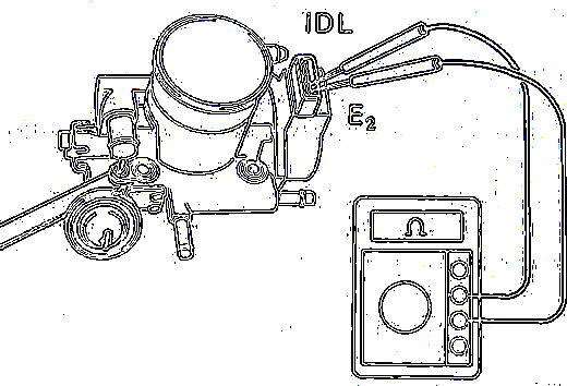
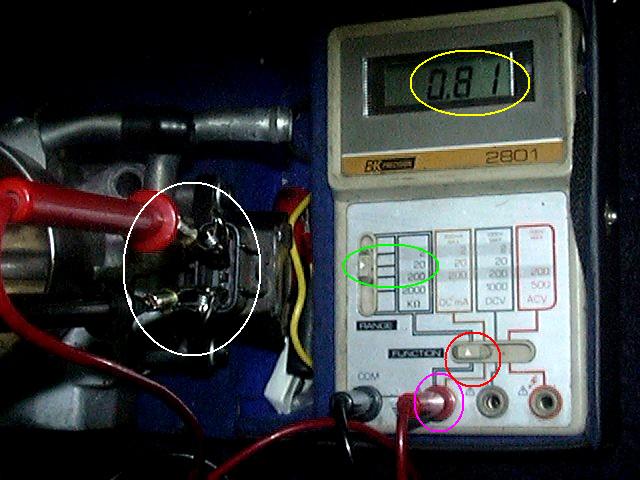
And shown in picture #5 is the proper ohm meter connection and use. If you are not familiar with the use of an ohm meter, the following paragraph will hopefully explain enough to get you started (click on the above image for a larger version that is easier to see if you need to):
-
The picture above shows a Digital Multi-Meter (DMM) connected to the
TPS connector.
- In the WHITE circle, you can see the red probe connected to the VTA terminal and the black probe connected to the E2 terminal of the TPS connector.
-
In the RED circle, you can see the DMM Function selector switch set to
the K-Ohm (Kilo Ohms) mode:
- Note, this may vary on different meters, some have a dial to select both the reading and range and some automatically select everything for you. Consult your meter's usage guide for more details.
-
In the MAGENTA circle, you can see how the red probe is inserted into
the Ohm/Amp plug. To see the flow, follow the heavy gray line from the
red Ohm plug, through the pointer on the Function switch to the K-Ohm
Range selector (more on that later).
- Again, this may vary with different meters, some meters internally switch the probe connections based upon the Function setting.
-
Why the different plugs on this meter?
-
A meter essentially measures current. A typical meter might read full
scale with 1 mA (0.001 amps) of current flowing through it. So, to
measure current, it is simply a matter of putting the meter in series
with the load and let the current flow through the meter (where is is
measured) and through the load. Range switching is done with shunts to
pull off only a fraction of the load current through the meter. So if
you only let 1/1000th of the current flow through the meter, a 1mA
reading would equal 1.0 amps of real current (0.001 * 1000 = 1.0).
- Thus the Red-Black plug connection is direct connection to the internal current meter.
-
To measure DC voltage, you put the meter in parallel with the load and
add a resistor in series with the meter to limit the flow of current.
So, if you put a 1000 ohm resistor in series with the 0.001 amp meter
and put 1.0 volts across the two, you would have 1.0/1000 or 0.001 amps
flowing through the meter. If the display reading were scaled to read
1.0 (at full scale), you would see 1.0 volts, or the proper reading.
- Thus the Gray-Black plugs make a connection to this internal series current-limiting resistance.
-
To measure AC voltage, you need to add a diode in series with the meter
to convert the AC voltage to DC so that the digital meter can read a
steady voltage. If the diode were not there to rectify the alternating
voltage, the reading from the meter would just appear to be a random
series of numbers.
- Thus the Orange-Black plugs make the connection through the internal rectifying diode.
-
And finally, the resistance (or ohms) function requires that some
voltage source (from the meter's internal battery) is needed to drive a
current through the external resistance and the meter to complete the
circuit. This connection is basically the same as the current measuring
connection (that is why the same Red-Black plugs are used) and when
Ohms is selected, the internal battery voltage is applied to the
circuit. So, if the internal voltage is 1.0 volts and you apply that
across a 1000 ohm resistor, 0.001 amps of current will flow and a full
scale reading of 1.0 (K-Ohms) is displayed.
- Note that when measuring ohms, there must be no power in the circuit you are measuring, otherwise you will get either erroneous readings (due to not knowing the voltage value) or worse you will damage the meter by forcing too much current through it's sensitive circuits.
-
A meter essentially measures current. A typical meter might read full
scale with 1 mA (0.001 amps) of current flowing through it. So, to
measure current, it is simply a matter of putting the meter in series
with the load and let the current flow through the meter (where is is
measured) and through the load. Range switching is done with shunts to
pull off only a fraction of the load current through the meter. So if
you only let 1/1000th of the current flow through the meter, a 1mA
reading would equal 1.0 amps of real current (0.001 * 1000 = 1.0).
-
Then the GREEN oval shows the K-Ohms Range selector in the 20 (K-Ohms)
range. This means that the full scale reading on the meter will be
20.000 (K Ohms) or 20,000 Ohms.
- Again, this may vary from meter to meter, some meters use an 1X - 10X - 100X - 1000X and so on multiplier that you must multiply the reading by to get the actual value. So a reading of 20 on the 1X scale is 20.0, while on the 1000X scale is 20,000.0.
-
So, finally to the reading on the display (circled in YELLOW), which in
this case is 0.81. In order to convert that decimal number to the
proper units, you must traverse the meter settings to get that all
correct:
- 0.81 on the 20K range is the same as 0.81 (K ohms) or 810 and since it is on the ohms function, the correct reading is 810 ohms.
- This 20K range is somewhat similar to a meter that had a 1000X multiplier, thus a reading of 0.81 * 1000 = 810. So it is important to not confuse ranges and multipliers, since if you interpreted the 20K range as a 20K (or 20,000X) multiplier, you would be off by a factor of 20!!!
- Also note that on the 20K range, the least significant digit is only good to 10 ohms. This as you go up in range, the accuracy/resolution of the meter goes down. It is therefore important to select the meter range just big enough to capture the range of values you expect to read, but no bigger than necessary. For the TPS, resistance range from about 500 up to 10,000 ohms, so the 20K range is ideal.
|
|
| Figure 2: Throttle Position Sensor (TPS) | Figure 3: TPS Adjustment |
Now, on to testing and adjusting the TPS. Table 1 lists the adjustment specifications for the early (1985-1995) TPS. There are slightly different measurements for the later model units. If someone knows the engine date at which the change below took effect, drop me an e-mail. My guess is the change took place with the change in the throttle body, early trucks TB is angled downwards, later trucks are horizontal. Refer to the above figures for TPS terminal layout and ohm meter connections. If in doubt about the layout of the terminals, an easy way to identify the proper orientation is to identify the VTA-E2 terminal pairs. E2 is at one end of the TPS connector or the other. VTA is one pin in from the opposite end. The VTA-E2 signal varies from a few hundred to a few thousand ohms as the TPS moves through it's range or travel. So, try one end of the TPS connector for E2 and see if the resistance varies properly, if not, try the other end. Once the E2 end of the connector is identified, the rest of the pins should be laid out as indicated in Figure 2.
Note: There is some variation in the "exact" resistance values among the various years, but in general test 1 should be a low resistance, under 1K (or a few K) ohms. Test 2 is under 2300 ohms, test 3 is open cicruit and tests 4 and 5 will be higher resistance, fabove 3000 ohms, more or less. Looking at these values, 2300 ohms seems to be the transition point where the ECU switches between a logic level of 0 and 1. Anythng under 2300 ohms is sensed as a logic level 0 and anything over 2300 ohms is a logic evel 1. Nor, right around 2300, things get a bit fuzzy, so that's why the low resistance readings are generally well below 2300 and the higher resistance readings are much larger than 2300.
| Test | Clearance between lever and stop screw |
Between terminals | Resistance / '85-'88* (ohms) |
Resistance / '89 (ohms) |
Resistance / '90*-'95 (ohms) |
| 1. | 0.00mm (0.000") | VTA - E2 | 200-800 | 200-800 | 470-6100 |
| 2. | 0.57mm (0.0224") | IDL - E2 | < 2.3K | < 2.3K | < 2.3K |
| 3. | 0.85mm (0.0335") | IDL - E2 | Open / Infinite | Open/Infinuite | Open / Infinite |
| 4. | Wide Open Throttle | VTA - E2 | 3.3K - 10.0K | 3.3K - 10.0K | 3.1K - 12.1 K |
| 5. | n / a | Vcc - E2 | 3.0K - 7.0K | 4.0K - 9.0K | 3.9K - 9.0K |
| Test | Clearance between lever and stop screw |
Between terminals | Resistance / '88 (ohms) |
Resistance / '89-'95 (ohms) |
| 1. | 0.00mm (0.000") or 0.50mm* |
VTA - E2 | 200-800 | 200-800 |
| 2. | 0.50mm (0.020") or 0.77mm* |
IDL - E2 | < 2.3K | < 2.3K |
| 3. | 0.77mm (0.030") or 0.85mm* |
IDL - E2 | Open / Infinite | Open / Infinite |
| 4. | Wide Open Throttle | VTA - E2 | 3.3K-10K | 3.3K-10K |
| 5. | n / a | Vcc - E2 | 3.0K - 7.0K | 4.0K - 9.0K |
How to tell if the TPS is good or not?
In the above tests, you are actually simulating various throttle positions and rotating the TPS on its base to achieve all the above conditions.
-
Test #1 simulates the closed throttle position, with
the throttle valve fully closed and the throttle stop lever in contact
with the throttle stop screw
- If you can't get this fully closed reading, make sure nothing is holding the throttle slightly open, like an improperly adjust throttle stop screw or dirt between the TPS back side actuator and the throttle body mechanism.
- If all is mechanically OK, then this reading can ba a go, no-go test, after all if you can't get a throttle closed reading with the TPS fully closed, then no amount of adjustment will help, since any adjustment is adding to the closed (0.00mm) throttle position.
-
Test #2 and #3 test the transition from idle to
normal operation
- Note that the exact feeler gauge values are not terribly important, use the closest gauge you have to the value, or stack two thinner gauges to make one the right thickness. Its unlikely you'll be able to adjust the TPS by hand to 0.001" anyway (in fact if you can get within 0.01" or 0.1mm you are doing pretty good!).
-
And note that there are a range of values for these tests on the V6
TPS. One might suspect that the "exact" throttle opening
where the IDL-E2 setting changes from below 2300 ohms to infinite makes
little difference. Rather it is the fact that it *does* change and does
so at a small throttle opening (under 1mm or so). Whether that happens
at 0.50mm, 0.70mm, or even 0.90mm probably makes little difference.
- Setting the TPS idle transition too close to 0 opening may result in a rough idling engine if the throttle were to stick open a tiny bit.
- Setting the transition too far out, would result in a sluggish throttle response, since the ECU would see a longer idle section on the TPS.
- Note: 0.80mm is about the thickness of a typical credit card, 0.50mm is about the thickness of a thinner plastic gift card, in case you lack a set of feeler gauges.
- So, if your TPS makes the idle transition (below 2300 to infinite) but you can only get it to do so at say 0.90mm instead of at 0.85mm, for example, does this mean the TPS is bad? Probably not, if everything else checks out, you may just be seeing the effect of the mfg. tolerances of the TPS and the throttle body stacking up and pushing the setting outside the "normal" range.
- Now, if the TPS never makes the idle transition (i.e. it reads infinite at all throttle openings, or it reads < 2300 ohms at all throttle openings), then likely it is bad.
-
And don't worry if THE GAP is not dead on. There are no "TPS
Police" that are going to pull you over and whip
out a set of feeler gauges to check your IDLe transition point.
- Heck, even the dreaded California smog tech's don't even look at the TPS as part of the visual check. As long as the engine is timed right (which relies on the TPS-IDL setting), that is all they care about.
-
Also, don't get hung up on getting some exact resistance reading.
- Less than 2300 (2.3K) ohms means just that, anything less than 2300 is fine; 2299 is less than 2300. 996.5 is less than 2300, 0.1 is less than 2300.
- Basically any reading in the range of 0.0 to 2299.9 is less than 2300. If your meter reads less than 2300, that is fine.
-
Test #4 tests the wide open throttle (WOT) setting.
- And you should see about the same VTA-E2 reading at wide open throttle as you read on Test #5 (below) on VCC-E2.
- This makes a good double check of your reading accuracy and repeatability.
-
Test #5 just measures the entire resistance of the
outer-most current track seen in Figure 2.
- This reading will be the same regardless of the throttle opening.
-
It can't be adjusted, so is basically a go or no-go reading.
- If the reading is within the specified range, it is OK, if not, it is not OK.
- So, how do you interpret the above test results and decide if your TPS is good or not? Well, here is how I interpreted the test results on mine:
- On my TPS, I measured a value of 500 (0.5K) ohms for test #1 and 5000 (5K) ohms for test #4 and the other values within spec. By setting the #1 resistance to roughly the middle of the range, the rest of the settings were dead on. One final test, not listed in the FSM, would be to run the TPS shaft from idle to WOT and watch the VTA-E2 resistance and make sure it increases monotonically, no drop outs or dead spots. If you observe abrupt resistance changes, the TPS could have a burned area on one of the current tracks. And finally, see the section here for some symptoms of a defective TPS - and if you do not have those symptoms, then it is likely OK as the ECU is the ultimate "judge" of goodness or badness.
See below for a detailed, step-by-step procedure for adjusting the TPS:
Throttle Position Sensor IDL-E2 Adjustment Procedure (courtesy of Frankenyota):
- Loosen both screws attaching TPS to throttle body.
-
Attach multi-meter to TPS terminals IDL and E2 (the bottom two
terminals on the TPS).
- You can use alligator clips to make this easier or use small ¼" lengths of vacuum hose to hold them on
- Insert 0.85mm (22RE) or 0.77mm (3VZE) feeler gauge between throttle stop screw and throttle plate (see picture)
- Move TPS body CW/CCW until ohms reading on multi-meter is infinite (open)
- Move the TPS body very slowly CCW until you find the end of the resistive strip, the meter will indicate <2.3K ohms of resistance
- Move the TPS body extremely slowly in the CW direction until the meter goes to open/infinite again
- Tighten the top TPS screw being very careful not to disturb the adjustment
- Remove the feeler gauge and insert a 0.57mm (22RE) or 0.50mm (3VZE) feeler gauge
-
The meter should (hopefully) indicate between 0 and 2.3K ohms of
resistance.
- If it does tighten the bottom screw and reconnect the electrical connector.
- If not go back to step 4 and try again
-
To check whether the adjustment was successful start the engine and
insert the timing test jumper.
- If the idle speed decreases audibly it is working normally.
While the above tests performed at the TPS itself do verify that the sensor itself it functioning, it does not test the continuity of the wiring in the harness that ultimately connects the TPS signals to the ECU. If TPS problems are suspected and the TPS itself checks out fine, then repeat the above tests at the ECU connector pins to verify they are reaching the ECU properly.
[Back to the top]
Troubleshooting:
Symptoms of a bad or misadjusted TPS include:
-
Inability to correctly set base ignition timing:
- i.e. you jumper the timing check connector and the idle and timing don't change
-
Varying idle speed, unstable idle or even misfiring at idle:
- This can happen because if the IDLe-E2 contact closure is not detected, the ECU is "running the engine real slow" vs. entering the stable idle mode. At low RPM and load, all the typical ECU sensor inputs may not be accurate and the ECU is trying to guess what is going on and adjust engine parameters on the fly. In normal idle, the ECU likely has a sort of pre-programmed loop it enters and ignores a lot of the sensor "noise".
- Note that a low coolant level can affect this as well, if air pockets reach the temperature sender, the ECU can get false readings of engine temperature and alternate between cold and warm idle speeds.
- Hesitation while accelerating:
- Poor fuel economy:
Seemingly unrelated systems can also be affected by a malfunctioning TPS, including Electronically Controlled Transmissions (ECT). Problems can include poor shifting and hunting between gears due to the engine computer seeing apparent throttle position changes coming from a flaky TPS. Since it is the TPS that tells the engine's ECU that you are idle, if that setting is off, setting timing can be difficult, since insertion of the timing check jumper won't have any affect on the engine.
And it is this very simple test that can be the ultimate test of the idle circuit of the TPS. If the ECU responds to the timing test jumper as it should with your TPS connected, it is "good" per your ECU. It is not like the ECU is sitting there with an ohm meter and if it sees 800.1 ohms on the IDL-E2 circuit, it won't recognize the idle signal. Likely there is some slack in the resistance ranges Toyota publishes. They are basically saying that anything less than 800 ohms will always work, but it may work above 800 ohms but it is not guaranteed. So if it works, great, if not, get a new TPS.
So, how does a TPS fail? Most likely one of two things will cause a TPS to fail. If you look inside one, you'll see it basically consists of a printed circuit board with a combination of conductive and resistive strips in a circular pattern, over which wiper contacts slide. This serves to generate the various resistance readings at varying throttle positions. The usual failure is for what used to be a low resistance to become an open connection (i.e. infinite resistance or ohms on a meter).
Upon visual investigation, its usually the case that the contact area on the PC board is burnt or dirty, leading to the open circuit reading. Putting too high a current through the TPS circuit (possibly due to a short circuit in the engine wiring harness) could lead to contact burning, but more likely is that a foreign substance entered the TPS and initiated the problem. A common cause of this is using throttle body cleaner in the throttle body without removing the TPS. The cleaner can wick into the TPS via the actuator that rotates the TPS. The cleaner can attach the PC board and components and cause it to fail. If cleaning the throttle body, be sure to remove the TPS, and also try to avoid getting engine cleaner and water on the TPS, its not totally sealed.
When re-installing the TPS, one handy tip is to replace the stock screws with allen head screws, the you can use a ball-headed wrench to access the screws while the throttle body is in place. Another tip for removing the throttle body is that if you keep the radiator cap on and use a bolt to plug the coolant hose that connect to it, there is no need to drain the cooling system as the Factory Service Manual recommends. You may lose a few ounces of coolant, but its no big deal.
If the TPS checks out fine, but you still suspect TPS problems, you should also check out the TPS connections to the ECU itself. You can have a perfect TPS, but if there is a wiring problem between it and the ECU, there will still be a problem.
And the way to ultimately test this out is to look at the TPS the way the ECU "sees" it. That is with the resultant voltages that appear at the ECU inputs while the engine is running. Why not do these tests first? Well you could, but they are harder to do since you need to hook up wires to sample ECU input signals and then monitor them with the engine running, or at least with power applied to everything (i.e. the ignition on). But the FSM lists the test points and voltages you should use and how to interpret them. But the basic jist is to measure the voltage at VTA to ground (see connector pin out below) and observe that voltage over the range of throttle positions. At idle, you should less than 0.5 volts and it should smoothly increase to about 5.0 volts at wide open throttle. And the IDL to ground voltage should be near 0 volts at idle and close to the battery voltage at anything off of idle. And you can use this 0V to 12V transition point to adjust the IDLe setting on the TPS. Of course, this is most precise but also the hardest to do since you are checking the voltage from inside the passenger foot well and adjusting the TPS in the engine bay, so unless you have a trained helper, it is not the easiest way to proceed. If you are having suspected TPS-related issues while driving, you might consider hard wiring up some test points off the ECU and then setting up a volt meter in the driver's compartment to observe or even fancier, set up a data logging system with a laptop and record the signals and look at them closely at a later point.
ECU Connector Pinouts:
|
|
|
| Pin | Input/Output | Connects To | Description |
| E01 | . | . | . |
| E01 | . | . | . |
| No10 | Output | Fuel Injector | Grounding Connection |
| No20 | Output | Fuel Injector | Grounding Connection |
| STA | . | . | . |
| IGt | . | Ignitor | IGt signal |
| Vf | . | . | . |
| E1 | . | . | ECU Ground connection, shared with ignitor |
| NSW | . | . | . |
| n/c | n/a | n/a | Not Connected |
| Pin | Input/Output | Connects To | Description |
| Fpu | . | . | . |
| ACV | . | . | . |
| W | . | . | . |
| n/c | n/a | n/a | Not Connected |
| T | . | . | . |
| TSW | . | . | . |
| IDL | Input | TPS | TPS IDLe contact |
| n/c | . | . | Not Connected |
| IGf | . | Ignitor | Ignitor IGf signal |
| E2 | . | . | . |
| n/c | . | . | Not Connected |
| Ox | Input | Oxygen Sensor | . |
| n/c | . | . | Not Connected |
| Vcc | . | . | . |
| KNK | Input | Knock Sensor | . |
| VTA | . | . | . |
| Ne | . | Ignitor | Ne signal |
| THW | . | . | . |
| Pin | Input/Output | Connects To | Description |
| n/c | n/a | n/a | Not Connected |
| n/c | n/a | n/a | Not Connected |
| n/c | n/a | n/a | Not Connected |
| n/c | n/a | n/a | Not Connected |
| Vc | . | . | . |
| E21 | . | . | . |
| Vs | . | . | . |
| 4WD | Input | 4WD Switch | In transfer case |
| THA | . | . | . |
| SPD | . | . | . |
| BATT | . | . | . |
| B/K | . | . | . |
| +B1 | . | . | . |
| +B | . | . | . |
[Back to the top]
Other TPS/EFI related information:
- A write up on TPS operation is available on the ORC Toyota Tech section
- Some tips on Air Flow Meter and TPS tweaks on the Celicas.org web page
- An extensive collection of technical articles is available at AutoShop101.com
Visitor # 766023 since 18.MAY.2002
[Initial creation: 24.Jan.2000][Last updated: 18.December.2022 ]