
Installation Instructions
Idler Arm Bushings, Toyota 4WD 1986-1995 Pickup and 4Runner, Hilux and Hilux Surf models
See also:
- 4WD Idler Arm removal and installation instructions
- YouTube video of the installation/rebuild process:
- If you purchased an idler arm with pre-installed bushings, skip to step #7...
USE OF THESE INSTRUCTIONS IS AT YOUR OWN RISK
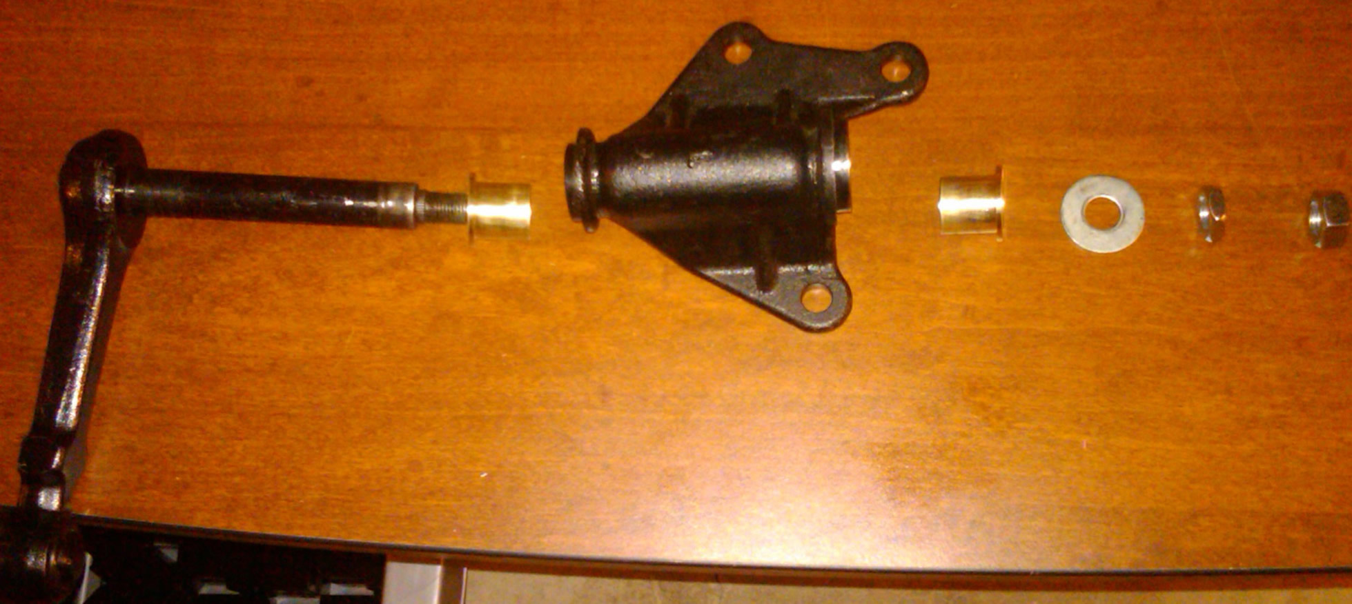
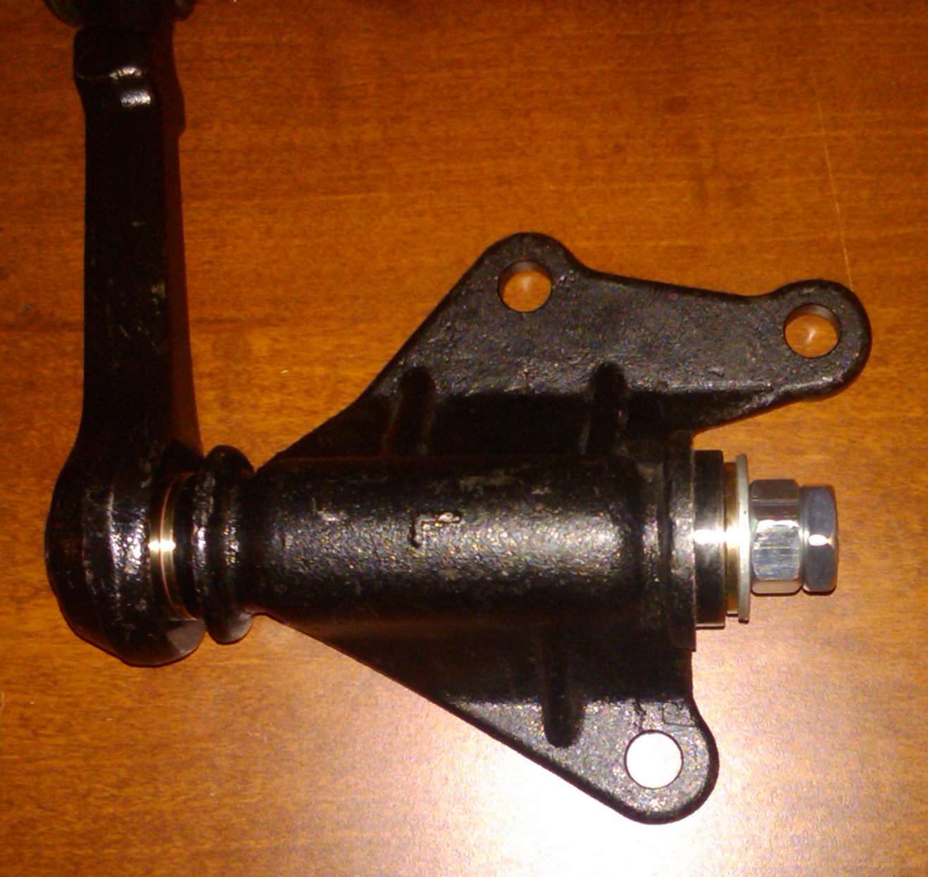
When installing this product, the installer is the final manufacturer of his or her vehicle. Installation and use of this product is at the risk of the installer. 4Crawler Offroad assumes no responsibility for any damages, to person, property, or any other sort incurred as a result of the use, mis-use, misunderstanding, inaccuracy or incompleteness of these Instructions, taken in whole or in part, or the products to which they may directly or indirectly pertain. The liability of 4Crawler Offroad, its affiliates, members and employees is solely limited to the providing a product of accurate dimension. What the buyer, installer, user, or any other person Does with product purchased from 4Crawler Offroad is done at their own risk and responsibility. Furthermore, 4Crawler Offroad Products does not guarantee the completeness or accuracy of the instructions contained herein. Below are the parts required for an entire idler arm assembly laid out in the order in which they are installed from left to right.
- Idler Arm: 4WD 4Runner/Pickup Idler Arm,
-
Bushings: Idler Bushings (2) - included in the bushing kit
- Optional: Brass shim stock for building up shaft diameter
- Washer/nut - from idler arm assembly
-
M14-1.5 flange nut and thin jam nut included in the bushing kit
- Optional: Shim washers for adjusting bushing clearance
Installation Notes:
- Remove the idler arm from the vehicle, if replacing the old idler arm.
-
Use a tie rod puller or pickle fork to remove the rod end from the
idler arm.
- Then remove the 3 bolts holding the arm to the frame.
- You can also leave the idler arm in place on the frame as that may provide the leverage to allow you to loosen the retaining nut on the end of the shaft.
- This is a good option if you already have an arm compatible with the new bushings.
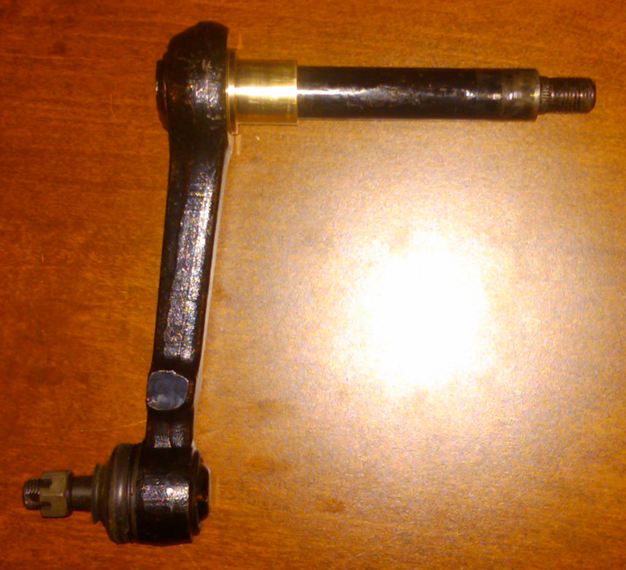
- 1. Disassemble the idler arm.
-
You can use a small flat blade screwdriver, stiff putty knife or
similar tool to pry off the end cap.
- Loosen and remove the nut on the end and slide the shaft out of the upper and lower bushings.
- You can keep these bushings for spares if you are starting with a new idler arm.
- Again, this can be done either in a vise on the bench or bolted to the frame of the vehicle.
- Clean the idler shaft and housing of any debris before installing bushings.
- Do not hit the bushings with a hammer or similar object.
- If one must tap a bushing into place, use a socket with a diameter similar to that of the bushing and tap the socket gently.
- You may find filing or sanding down the outer diameter of the bushings and/or using a small sanding drum (like on a Dremel or cordless drill) to open up the inside diameter of the idler arm housing is the best option for fitting the bushings in place.
- Clean off any sanding debris and test fit the bushings periodically until they just slide into place.
- Loosen and remove the nut on the end and slide the shaft out of the upper and lower bushings.
- 2. Slide one bushing over the idler shaft.
-
It might be necessary to use the idler housing to push the bushing onto
the shaft.
- This is fine since the next step is to install the idler housing.
- The bushings should fit snugly, but not be jammed on so tight that they will not move.
- If you feel the fit is too tight, use some fine emery cloth (sandpaper) or a rotary tool and sanding drum and slightly sand down the outer surface of the round shaft to smooth and polish any rough spots.
- One easy way to do this is to wrap the shaft in some emery cloth or metal sand paper.
- Then grasp that paper wrapped shaft and swing the idler arm around like one of those old holiday noise makers.
- You are simply trying to remove any high spots and polish up the metal if it's a little rough.
- Wipe down the shaft with some light oil on a cloth to remove any sanding debris and test the bushing fit.
- If you find the bushings fit loosely on the idler arm shaft and you purchased the optional shim material, you'll need to trim that material to size.
- Be careful as the metal may have sharp edges and corners, so wear gloves if needed.
- First insert both bushings into the idler arm housing to get a measurement of the overall height from top flange to bottom flange.
- You'll want to trim the shim stock to just a little less than this height.
- Then wrap the shim stock around the shaft and mark where it overlaps.
- You can then trim the width to just allow the shim material to encircle the shaft in one layer.
- Then coil up the shim stock, insert it inside the idler arm bushing and try to slide the shaft inside.
- If the fit is too tight, you can trim the stock a little narrower to make more room between the shaft and bushings.
- The thicker shim stock is approx. 0.009" thick, so adds up to 0.018" to the overall shaft diameter, the thinner stock is 0.004" thick and two wraps would be 0.008".
- You might want to apply some lubrication to the shaft and shim stock prior to sliding it in for the final assembly. If the fit is too tight with a full circle of shim stock,
- You can trim the shim down in width so it only circles part way around the shaft.
- This is fine since the next step is to install the idler housing.
3. Install the idler housing. Again, the bronze bushing should fit snugly in the housing but you should not have to force it. If you find the fit is too tight, spend some time with a small round file, emery cloth or a small drum sander in a Dremel tool to sand down any burrs inside the housing. The idea being that if you can slide the parts together easily, you'll also be able to slide them apart easily if you ever have to take the arm apart in the future. So a few minutes spent on this first assembly will pay off in the long run.
If using the shim stock, you'll want to size it first them form it to fit inside the bushings. We pre-cut the shim stock roughly to dimension but you may need to trim it to length and width to exactly fit your idler arm and that is best done first. Then form the shim stock to fit the idler arm shaft. You can also slide it through one of the bushings a few times to help form it. Coil that up and stick it through the one bushing and down into the housing. Then slide the other bushing in around the shim stock on the other end of the housing. Finally slide the shaft of the idler arm inside the shim stock taking care to not damage the material as you slide the arm in. Once the shaft is in place, the shim material will be trapped between the top and bottom of the shaft and it won't fall out.
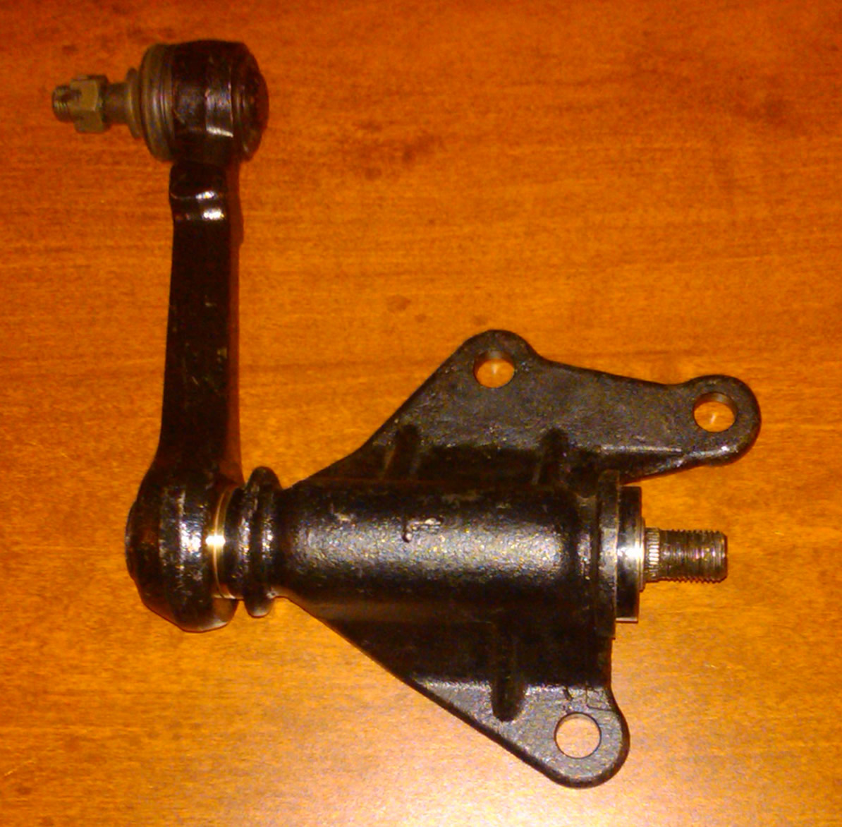
4. Install the next bushing. It might be necessary to gently tap the bushing into position until enough threads are exposed to install the washer and get the 7mm nut started. (the order of the hex nuts is not important). Again, if you need to tap the bushing into place, make sure to do so gently. If you find you need to use heavy force, stop and pull the bushing out and look for signs of inference around the outside (scratches or shiny marks). If found, find what is causing the tight fit inside the housing and clean that up with a file or sand paper before proceeding.
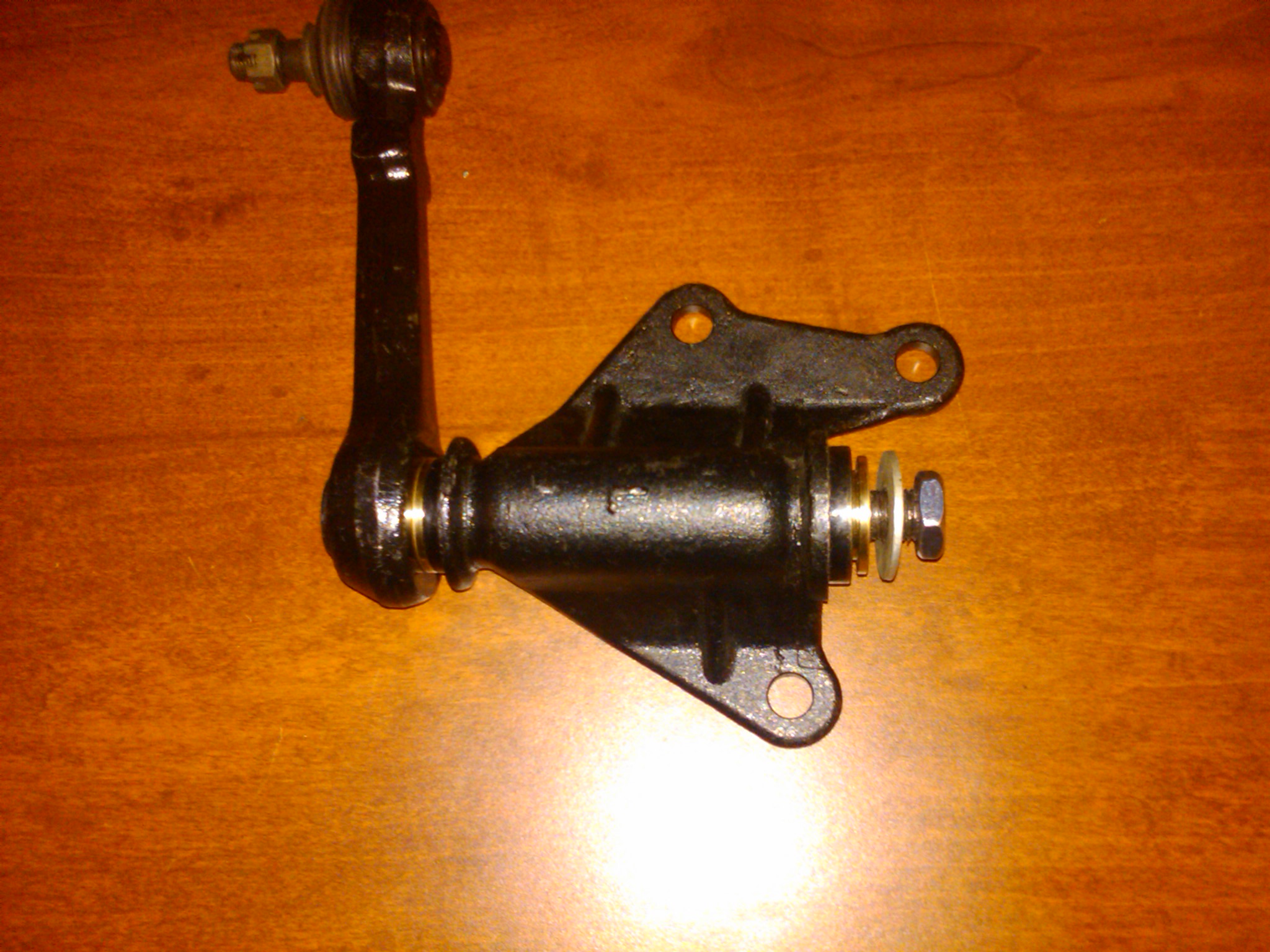
5. You have 2 options on nuts and washers:
1. Use the new flange nut in place of the original nut and washer
2. Use the original hex nut to push the washer and bushing into position.
In either case, tighten until one can feel the drag on the shaft as one tries to rotate it increase. With the flange nut, you can tighten the nut until the shaft won't move by hand and then back it off about 1/2 turn.
For the shim washer kit, if purchased, you'll be stacking shim washers onto the threaded end of the shaft until you achieve the desired idler arm drag with the nut fully tight. We recommend starting with the 2mm shim first, then adding thinner shims in succession. If the arm doesn't move freely with the nut fully tightened, remove the nut and add the next thinnest shim and repeat. If you find the arm moves very easily, you'll need to remove the last shim and replace it with a thinner one. For example, your sequence might be 2mm (tight), 3mm (tight), 3.5mm(loose), then remove the 0.5mm and replace with 2 of the 0.2mm shims for 3.4mm overall. If that's too loose, you could remove a 0.2mm and replace with the 0.1mm shim washer. Hold onto the unused shims in case you need to fine tune the adjustment later. With the shim washer kit installed, you can torque down the nut to facotry specification if you want.
6. If not using the original nylock nut, install the second hex nut finger tight. This nut is the jam nut that will be used to lock the adjustment of the first nut in place. If your arm comes with a NyLock lock nut, you may use that as you prefer. Both options will work fine. Some arms come with a plain hex nut. In that case, you'll want to use a jam nut along with that in order to get the right amount of pre-load on the bronze bushings. In any event, hold onto the unused nut(s) and keep them as well as the old plastic bushings as spares.
7. Re-install the idler arm onto the vehicle, you can see the links below for details. If you purchased an idler arm with the bushing pre-installed, this is where you'll begin. We leave the dust cap on top of the arm loosely fitted so that you can take it off if needed to adjust the tension.
8. The next step typically takes two or three tries to get right. Tighten the jam nut and see that the idler can be moved by hand. It is Ok if it is difficult to move by hand, but one should be able to move it about 45 degrees. If it is too hard, it is too tight. Loosen the first nut and re-tighten the second. Repeat until there is more drag than if the hardware is loose but not so much one cannot move the idler arm by hand. If you want to ensure the jam nut stays in place, you can either add a thread locking compound to the jam nut threads before installing or you can use something like a penetrating thread locker (like green Loctite) on the jam nut after tightening it down.
9. If you find that the steering is a little too stiff or of you find that it does not return to center like before, you may have tightened the nuts a little too tight. You can either back them off a little or let the bushings wear in and loosen up in time. And it is a good idea to check the tightness of the jam nut after a bit of driving as things may settle into place with the road vibrations and a little looseness can develop. If you hear or feel any clunking in the steering, you should be sure and check the idler arm for play and adjust it back to the above conditions. Once you have everything settled into place and the nuts properly tightened, the idler arm should be set for years of trouble-free use. You can now tap the dust cap onto the top of the idler arm with a rubber mallet.
- Here are some other on-line links with more information on removing, rebuilding and reinstalling the idler arm:
-
http://www.4x4wire.com/toyota/maintenance/idler/
- http://www.youtube.com/watch?v=vXLDTkD2Ap4
USE OF THESE INSTRUCTIONS IS AT YOUR OWN RISK
When installing this product, the installer is the final manufacturer of his or her vehicle. Installation and use of this product is at the risk of the installer. 4Crawler Offroad assumes no responsibility for any damages, to person, property, or any other sort incurred as a result of the use, mis-use, misunderstanding, inaccuracy or incompleteness of these Instructions, taken in whole or in part, or the products to which they may directly or indirectly pertain. The liability of 4Crawler Offroad, its affiliates, members and employees is solely limited to the providing a product of accurate dimension. What the buyer, installer, user, or any other person Does with product purchased from 4Crawler Offroad is done at their own risk and responsibility. Furthermore, 4Crawler Offroad does not guarantee the completeness or accuracy of the instructions contained herein.