
Volkswagen produces a series of 4-, 5- and 6-cylinder naturally aspirated Diesel engines of the swirlchamber type since 1978. On this basis the development of a 4- and 5-cylinder turbocharged engine was begun. The paper describes the design and development highlights of the 4-cylinder engine with a nominal power of 51 kW and the 5-cylinder version with 64 kW power output. The performance characteristic of the major engine components as well as exhaust emissions and fuel consumption, measured on the engine dynamometer and in actual vehicle installation, are reported.
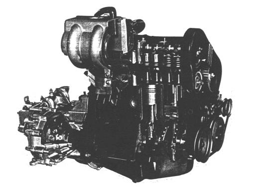
In the fall of 1976, Volkswagen introduced its first 4-cylinder Diesel engine, a swirlchamber design with a stroke of 80 mm and a bore of 76.5 mm, giving a displaced volume of 1471 cc. Cutaway models of this engine with its transmission are shown from the injection pump side in Figure 1, and from the manifold side in Figure 2. The nominal power was 50 hp at 5000 rpm. The fundamentals of this development have been described by P. Hofbauer and K. Sator in Reference (1) where on the basis of a systems analysis arguments were given explaining why this concept had been chosen from a number of alternatives.
Two years later, the development of a 5- and a 6-cylinder Diesel engine was completed. Both engine types used the same combustion system as developed for the 4-cylinder engine. Thus, in addition to the powerplants for the Volkswagen Rabbit and Dasher vehicles, Diesel engines became available for the AUDI 5000 and the Volkswagen Truck. Since 1979, the 6-cylinder Diesel engine has been sold to VOLVO for a passenger car application. With a displacement of 400 cc per cylinder and the somewhat smaller 368 cc per cylinder swept volume of the 4-cylinder engine, three conceptually very similar powerplants have been obtained. The development of the 5- and 6-cylinder Diesel engines has been described by K. Sator, W. Buttgereit and U. Sturzebecher in Reference (2).
In the fall of 1980 the engine displacement of the 4-cylinder engine was increased by lengthening the engine stroke from 80 to 86.4 mm. In doing this, a true family of engines from 4- to 6-cylinders was obtained with a large percentage of common parts.
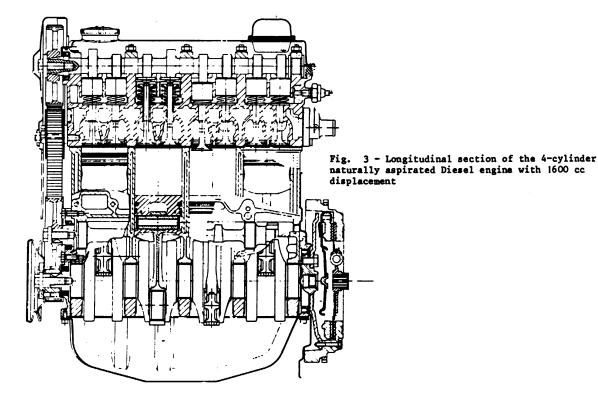
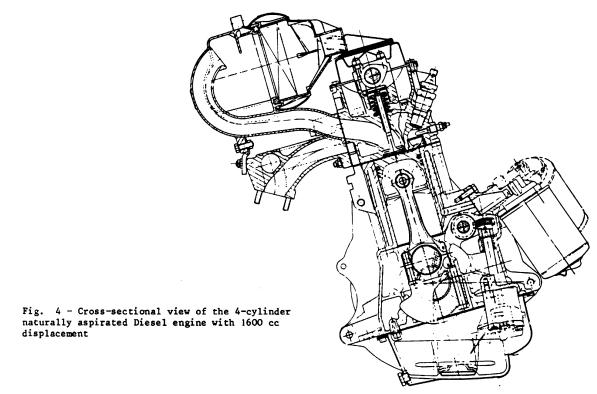
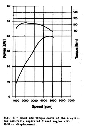
The design details of the base 4-cylinder engine of this family are shown in the longitudinal and cross-sectional views of Figures 3 and 4 respectively. Its power and the torque curves are plotted versus engine speed in Figure 5. Nominal power was 40 kW or 54 hp at 4800 rpm. The maximum torque is 102 Nm at 2000 rpm.
At the time when the displacement of the 4-cylinder engine was increased, a number of changes and improvements were made. Due to the longer stroke a new connecting rod was designed and the distance between the connecting rod bolts increased to 61.5 mm. The small end hole was enlarged to accomodate the increase in piston pin diameter from 22 to 24 mm. Thus, the small end bearing became a common part with the 5- and 6- cylinder engine. Further, the oil filter support was modified so that a single design could be used with both the Otto- and Diesel engine.
The latest development of the naturally aspirated Diesel engine was concluded in early 1981 with an application to the Volkswagen Transporter and Microbus. Engine power had been changed to 37 kW at 4200 rpm. The base engine remained the same but peripheral parts were modified because of the limited engine compartment space. The engine had to be tilted 50 degrees. Modifications concerning engine and vehicle related data were described by H. Steinecke and K. Sator in Reference (3).
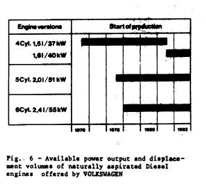
A summary of naturally aspirated Diesel engine production is given in Figure 6. The demand for small high speed Diesel engines has increased significantly over the last few years, as shown in Figure 7. In the first half of 1981 2600 naturally aspirated Diesel engines were produced every day. Diesel engines currently hold 40 X of the total production of watercooled engines in the Volkswagen Corporation.

The common argument, that a passenger car with a Diesel engine cannot satisfy the requirements of todays traffic conditions, has been challenged with the introduction of the modern high speed naturally aspirated Diesel engine. In order to broaden the spectrum of available power output engines, the development of turbocharged Diesel adaptations of existing engines was begun. The aim was to combine the performance of the Otto engine with the economy of the well proven naturally aspirated Diesel engine.
Preliminary work in this direction was carried out in 1977 - 78 by the Volkswagen
Research Division. Concept studies resulted in the so-called Integrated Research Vehicle (IRVW) with a supercharged Diesel engine and a 5-speed transmission. The concept has been discussed by B. Wiedemann and P. Hofbauer in Reference (4).
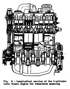
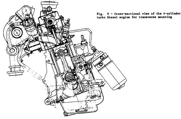
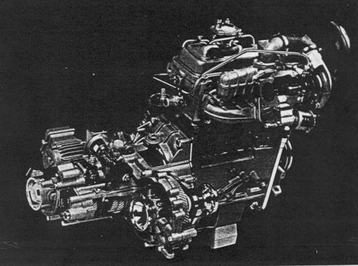
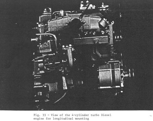
[Return to Table of Contents]The 4-cylinder turbocharged Diesel engine is designed as a powerplant for 5 vehicle models of VOLKSWACEN AUDI production. The engine is transversely mounted in the Rabbit and Jetta vehicles. The engine is mounted longitudinally across the front axle in the Dasher, Quantum and AUDI 4000. Because of different space restrictions in the engine compartment, the turbocharger unit is mounted in two different locations. Longitudinal and cross-sectional views through the transverse engine are shown in Figures 8 and 9 respectively. For comparison, a cross-sectional view of the longitudinal mounting is shown in Figure 10. The significant difference between the two mountings is the lower position of the turbocharger unit in the longitudinal mounting, which allows for a smooth connection between turbine exit and the exhaust system.

The power and torque curve shown in Figure 11 are identical for both mountings. Nominal power is 51 kW or 70 HP at 4500 rpm. Maximum torque is 133 Nm at 2600 rpm. The engine displacement of 1588 cc results from a bore of 76.5 and a stroke of 86.4 mm. The compression ratio is 23:1.

The intake valve has a maximum valve lift of 8 mm. Intake opening is at 5 degrees aTDC and intake closing at 14 degrees aBDC where both timings are rated at 1 mm of camlift. The maximum valve lift of the exhaust valve is 9mm, with opening and closing at 27 degrees bBDC and ~ degrees bTDC respectively. Intake valve clearance is 0.2 to 0.3 mm, and exhaust valve clearance is 0.4 to 0.5 mm. All these geometrical dimensions are identical with that of the 4-cylinder naturally aspirated Diesel engine.
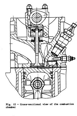
A cross-section through the combustion chamber with the position of the injection nozzle, glow plug and swirl chamber inrert, as well as the shape of the piston cavity can be seen in Figure 12. Numerous investigations on the combustion chamber parameters were carried out. For example the angle of the injection nozzle with respect to the cylinder axis, the position of the glow plug in longitudinal engine direction, as well as its penetration were optimized. Other parameter studies concerned the effect of the volume ratio between the swirlchamber, the cross-sectional shape and rise of the connecting port between the two combustion chambers and the sire of the injection port. By considering the best compromise of engine power, fuel consumption, soot formation and exhaust emissions the configuration shown in Figure 12 was obtained. Experimental results will be discussed later in this paper.
The distributor type BOSCH VE fuel injection pump was chosen and adapted with a boost pressure controlled full load stop (LDA), The working principle is assumed to be well known. The maximum fuel delivery is 0.0365 cc per stroke at full load at which injection timing is varied by 8 degrees of cam angle. Injection timing is set by measuring the position of the distributor plunger when the cylinder one piston is at top dead center. The distributor injection pump with LDA is shown schematically in Figure 13. The LDA determines the fuel quantity in the middle and upper engine speed range, corresponding to the boost pressure level. At very low engine speeds the LDA is not operational because the boost pressure is not sufficient to overcome the spring preload.
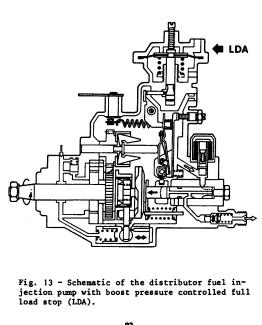
When the control pin moves vertically, the stop lever rotates and the control plate is pushed in the direction of greater fuel delivery, i.e. to match the increased charge air quantity. In case of a failure of the turbocharger, the base ratting becomes effective, resulting in smoke free combustion.
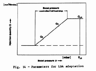
The main quantities which define the specifications of the LDA can be found in Figure 14. The rated full load speed is 2250 rpm. The high idle speed is at 2550 rpm.
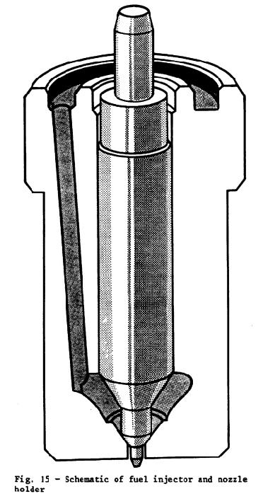
The fuel injection lines have an inner diameter of 2.25 and a length of 340 ms. BOSCH DNO SD 293 injection nozzles are used with an injection pressure of 155 bar, compared to 130 bar in the naturally aspirated Diesel engine. The pintle nozzle and a nozzle holder ore shown in Figure 15. The same injection nozzle type is used for the 4 and 5 cylinder turbocharged Diesel engines.
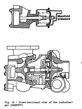
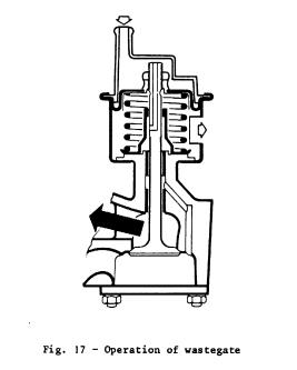
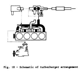
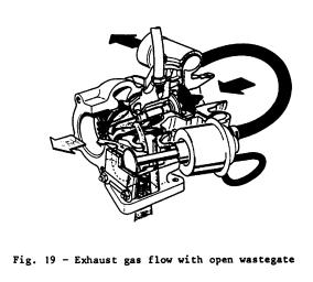
The turbocharger unit is adapted to small displacement engines. Turbochargers from GARRETT AIR RESEARCH (Figure 16) and KUHNLE KOPP and KAUSCH are used. Details of the wastegate can be seen in Figure 17. The turbine housing material has been optimized for the high exhaust gas temperature. Figure 18 shows a schematic of a turbocharger, engine and fuel injection pump arrangement, In the case of excessive boost pressure, the wastegate opens and the turbine receives only a portion of the hot exhaust gases while the remainder flows directly into the exhaust pipe. As a result, turbine and impeller speed are reduced and the designed boost pressure is maintained. The operation of a partially open wastegate is shown in Figure 19.
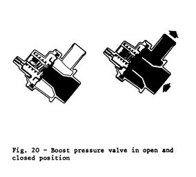
Should the wastegate valve not open, an excessive boost pressure opens a blow-off valve mounted at the intake entrance, at a pressure of 0.8 bar. Compressed air is then directed back into the intake stream. The arrangement of this blow-off valve and its operation in the closed and open positions are shown in Figure 20.
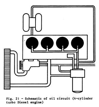
The oil circuit had to be adapted to the specific needs of the engine because of the higher thermal loading. In addition to the conventional pressurized lubrication system, oil lines with upwards directed jets are mounted in the crankcase at each cylinder to provide additional cooling of the piston bottoms. A lubrication circuit was also added for the turbocharger bearings. Both features are shown schematically in Figure 21. The oil from the turbocharger bearings flows back into the oil pan via a flexible tube. The oil pump capacity has been increased by approximately 15 % by an increase in the width of the pump gear from 26 to 30 mm. Before entering the oil fitter the oil flows through a heat exchanger, which is cooled by the engine coolant. Figure 22 shows the cooling of the piston bottom. This special oil cooling lowers critical piston temperatures by approximately 30 C.

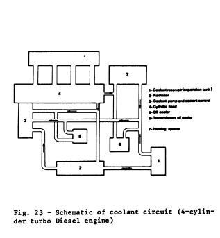
The complete engine cooling circuit is shown in Figure 23. As long as the thermostat is closed, coolant flows directly back to the water pump. The oil heat-exchanger, however, is in operation at all times, thereby reducing the engine warm-up time. For vehicles with an automatic transmission, part of the cooling flow is directed through an additional heat exchanger to cool the transmission fluid, before the coolant returns to the water pump.
Air induction takes place through an improved air filter with filtration and lower resistance than the naturally aspirated Diesel engine air filter, The air filter is mounted sideways on the vehicle body.
Gases from the crankcase are expanded in an oil separator mounted in the cylinder head cover. Oil droplets are separated and are directed back into the oil pan. Crankcase ventilation gases flow to the air filter via a pressure regulation valve. The system is completely closed. Additional modifications are briefly described here: The chemical and material properties of the cylinder head aluminum alloy have been optimized. The swirl chamber insert material also had to be adapted to the higher thermal load. For similar reasons the crankcase deck thickness has been increased and the region of the cylinder head-bolts was strengthened.
A number of changes were made to the crankshaft. The front end of the crankshaft was reinforced. The highly loaded crank-pin, at cylinder 4, has its radius induction hardened and the oil hole ground while radii at the other pins are roll-hardened. A torsional vibration damper is used.
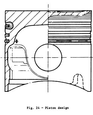
Oil cooled pistons with a diameter of 76.5mm and with a ringcarrier are being used. Near bottom dead center, oil injection tubes enter into the piston. This requires a notch in the piston skirt. Because of the higher stress in the piston pin region relief pockets have been cut out. Figure 24 shows the piston design.
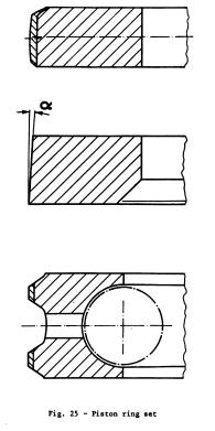
The top groove contains a rectangular ring with its contact face inclined to the cylinder wall thus providing a sharp lower edge to reduce blowby and oil consumption. The ring is made of high tensile cast graphite iron with a chrome surface 0.16 to 0.25 mm thick. The second groove is fitted with a tapered ring made of cast iron with a conical contact surface of 2,5 degrees. The design is of the reversed torsion ring type and helps to control blow-by and oil consumption even after long operation. The third groove is fitted with a beveled, spring loaded ring with contact surfaces hard chrome plated and profile ground, and a centerless ground tube-like spring, which is narrow wound near the ends. Because of the small height of only 3 mm a high degree of flexibility is obtained at a relatively low tangential force, while good oil control is maintained. The piston ring set is shown in Figure 25.
Intake and exhaust valves were modified for the higher loads. While the naturally aspirated Diesel engine uses CrSi 9 valve steel, a material with higher thermal stress was selected for the turbocharged Diesel. Valve seat wear has been reduced to acceptable values by proper selection of the valve seat material.
Because of the valve temperatures being approximately 100 to 150 C higher a better valve head material is also used for the exhaust valve. In order to prevent hot-corrosion a chromium-nickel-aluminum-plating is applied by the plasma technique.
Valve seat rings for both intake and exhaust are made of a high alloy casting material.
The crankshaft main bearings and the connecting rod bearings are of a three material type. They are identical with those of the naturally aspirated Diesel engine.
Materials for the exhaust manifold and the bolts for cylinder head and turbocharger mounting required modification.
[Return to Table of Contents]In describing the design of the 4-cylinder turbocharged Diesel engine, most new parts for the 5-cylinder turbocharged engine have already been discussed. In the following, the differences between the two engines are described.
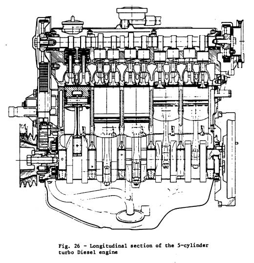
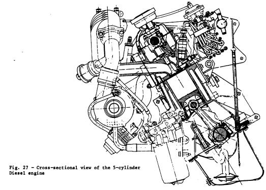
The longitudinal and the cross-sectional views of the 5-cylinder turbocharged Diesel engine are shown in Figures 26 and 27, The power and torque curves of the 5-cylinder engine can be seen in Figure 28. Maximum power output is obtained at 4500 rpm with 64 kW, maximum torque is obtained at 2750 rpm and measured as 172 Nm. The maximum mean effective pressure is 11.1 bar which is 4 % higher than that for the 4-cylinder turbocharged Diesel engine. The specific power output is identical for both engines at 32.2 kW/liter.

As in the case of the 4-cylinder engine the stroke is 86.4 and the bore is 76.5 mm, resulting in a total engine displacement of 1986 cc. The compression ratio is also 23:1.
The intake valve has a maximum valve lift of 8.5 mm. Valve timing at 1 mm cam lift is 5 degrees bTDC for opening and 21 degrees aBDC for closing. The maximum valve lift of the exhaust valve is 9 mm. The exhaust valve opens at 27 degrees bBDC and closes 5 degrees bTDC. The intake valve clearance is O.18 to 0.30 mm and the exhaust valve clearance is 0.38 to 0.50 mm, both measured at operating temperature.
The fuel injection pump again is of the distributor type from ROBERT BOSCH, equipped with the already mentioned boost pressure controlled full load stop (LDA). Injection lines have a length of 320 and an inner diameter of 2.25 mm. The fuel injection nozzles are identical with those from the 4-cylinder turbocharged Diesel engine.
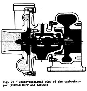
The turbocharger unit is of the type K 24 from KUHNLE KOPP and KAUSCH (KKK). The design of the K-type series is schematically shown in Figure 29.
The engine has a larger air filter with a higher degree of filtration and reduced intake pressure loss. The airfilter connects with the compressor by a rubber intake tube, as does the compressor with the intake manifold. The intake manifold is made of aluminum. The specially developed cylinder head gasket will be discussed later on.
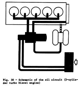
A schematic of the lubrication circuit is shown in Figure 30. Contrary to the 4-cylinder turbocharged Diesel engine, a thermostatically controlled oil to air cooler is used. The turbocharger bearings are supplied by a tube from the oil filter support. The return flow from the turbocharger is directed into the crankcase.
The direction of flow and the main components of the cooling system ore shown in Figure 31. Unlike the 4-cylinder package a water heated wax thermostat is attached to the injection pump to perform these three functions:


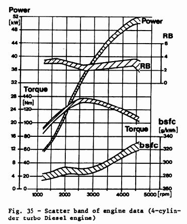
In Figure 35 the scatter bands for power output, engine torque, fuel consumption and exhaust opacity at full load are plotted versus engine speed for a number of pre-production engines. The following engine maps are representative for the optimization obtained during the last stage of the development. Figures 36, 37, 38, and 39 show the specific fuel consumption in g/kWh, the exhaust emissions of unburned hydrocarbons
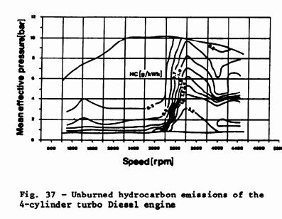
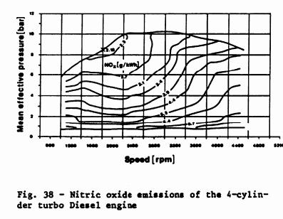
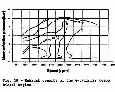
and nitric oxides, also in g/kWh, and the soot number in units of BOSCH, respectively, The minimum fuel consumption was measured at approximately 6 bar and at an engine speed of 1800 rpm with a value of 264 g/kWh. This figure is approximately equal to that of the naturally aspirated engine. The specific emissions of unburned hydrocarbons are very low and are less than 0.3 g/kWh in a large part of the engine map. Specific NO, emissions are at a minimum near full lord and at low engine speeds typical of Diesel engines. Figure 39 presents the map for the soot number with values below 1 BOSCH unit at engine speeds of less than 2200 rpm and mean effective pressures below 4 bar.
During the course of the combustion chamber optimization program the opening in the cylinder head between the injection nozzle and the swirl chamber was increased from 7 to 13 mm. The advantages for soot-number and fuel consumption are shown at 2000 and 3000 rpm and plotted versus start of injection, in Figure 40. This improvement was first found during an investigation of the 4-cylinder naturally aspirated Diesel engine and has later been checked and incorporated into the turbocharged Diesel engines.

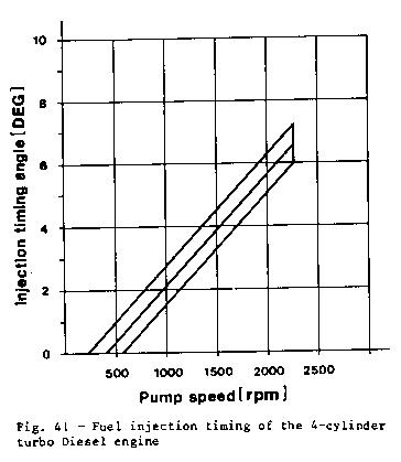
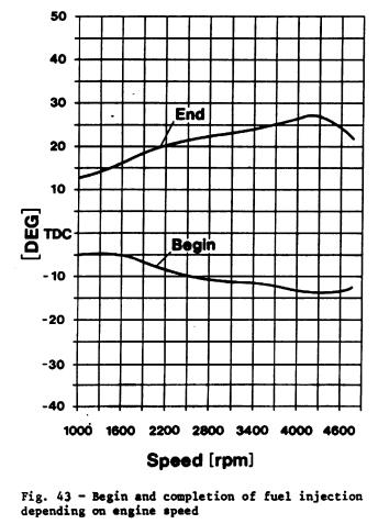
Figure 41 shows the allowable tolerance band of fuel injection timing depending on pump speed. The fuel injection system, consisting of the distributor fuel injection pump, the fuel injection fines, nozzles and nozzle holders are shown in Figure 42. Figure 43 indicates a typical development of start and end of injection depending on engine speed. The relationship shown was derived from measurement of the injection needle lift and is shown in more detail in Figure 44 for an engine speed of 2800 rpm and full engine load. Figure 44 also shows cylinder pressure development relative to top dead center.


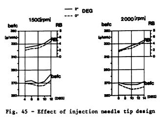
An extensive program has been carried out for the optimization of the fuel injection system. Only selected perimeters can be discussed here. One such parameter dealt with the effect of a cylindrical injection needle tip as compared to a 2 degree conical tip. It can be seen from Figure 45, why the cylindrical version has been given preference. Another parameter which has been studied is the plunger diameter size. A 10 mm diameter war compared with the regular 9 mm size. The larger diameter showed an increase in injection quantity and engine power output in the high speed range, while specific fuel consumption was reduced for nearly the same exhaust soot level.
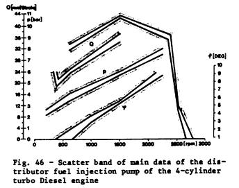
The scatter in typical fuel injection pump data is shown for 23 samples in Figure 46. Injection quantity with and without boost pressure, internal pump pressure and fuel injection timing are plotted versus pump speed.
For an evaluation of the specific turbocharger parameters, the impeller map can be examined in Figure 47. The boost pressure is plotted versus engine speed in Figure 48. Figure 49 gives additional information in the entire engine operating range were lines of constant boost pressure are plotted. Figure 50 shows lines of constant turbine inlet temperature and Figure 51 turbine exit temperature. The maximum turbine inlet temperature, which is difficult to measure, is approximately 820 C.

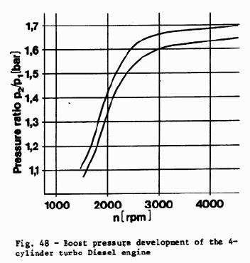
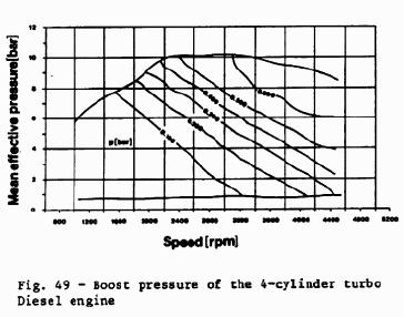

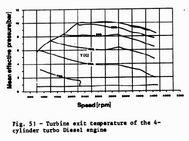
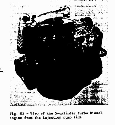
Figure 52 represents a view of the 5-cylinder turbocharged Diesel engine from the fuel injection pump side and Figure 53 shows a view from the turbocharger side.

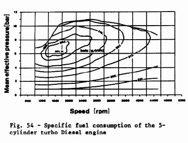
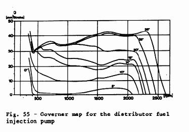
The specific fuel consumption map is plotted in Figure 54. The minimum is 261 g/kWh at 6 bar and 1800 rpm. The governor map of the 5-cylinder distributor fuel injection pump is plotted in Figure 55. Delivered fuel quantities depending on pump speed are given far constant fuel injection lever position in degrees. In the regions of high and low speed the governor curves have the generally known steep characteristic, while in the main region of operation the curves are approximately horizontal.
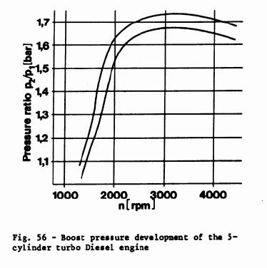
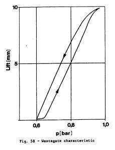
The boost pressure development of the 5-cylinder turbocharged Diesel engine can be seen in Figure 56. Upper and lower curve represent the expected scatter band for serial production. Boost pressure starts to develop at an engine speed of approximately 1250 rpm, which is somewhat lower than in the case of the 4-cylinder turbocharged Diesel engine. Curves of constant boost pressure are plotted in the engine map, Figure 57. The wastegate opening and closing movement is shown in Figure 58. The maximum lift is 10 mm.

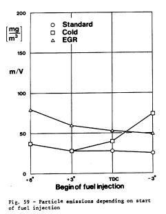
Particulate emissions were measured in the most common operating point of the City Driving Cycle. During the course of third program, the effects of early and late fuel injection relative to a standard setting, have been investigated. Two other effects were studied: low engine operating temperature and exhaust gas recirculation. Typical results for 2100 rpm and a mean effective pressure of 1.8 bar are shown in Figures 59, 60 and 61. In Figure 59, particulate emissions in mg per cubic meter of exhaust get flow, in Figure 60, the soot-number in BOSCH units and the specific fuel consumption in g/kWh, and in Figure 61 nitric-oxide and unburned hydrocarbon emissions in ppm are all plotted versus start of fuel delivery. It was generally found that fuel consumption and hydrocarbon emissions rise when fuel delivery is retarded. The effects on nitric oxide emissions and soot formation are to the contrary. Particulate emissions of a cold engine are equal to or somewhat higher than under standard conditions. Exhaust gas recirculation can lead to a considerable increase in particulate emissions. Relatively speaking this is also true when the soot-number is considered. The effects on nitric oxides and on hydrocarbon emissions confirm the relationship already established by other investigations. Detailed results of an optimized EGR system will be discussed at a later date.


The increase in stiffness between the cylinder head and the engine block, as well as a change in the tightening procedure for the cylinder head baits, are essential modifications required for the turbocharged Diesel engine. As already mentioned thread size was increased from 11 mm to 12 mm along with deck thickness. The tightening procedure was changed from torque controlled to angle controlled. This technique is applied to both the 4- and 5-cylinder turbocharged Diesel engines. Deflection measurements indicated that even under increased forces, deflections stayed well below the usual limits.
4- and 5-cylinder turbocharged Diesel engines are provided with a torsional vibration damper. The main goal was to dampen the critical 6th order at 4800 rpm. All other orders were less than +/- O.16 degrees crankangle. The problem was solved by design modifications and the proper damper material selection.
Extensive testing was done to optimize the cylinder head gasket in conjunction with the cylinder block modifications. The final design of the gasket is shown from top and bottom views in Figure 62. The proper combination in fiber, rubber and metal material had to be specifically selected. An essential feature of the gasket is the equalization of the pressure distribution, obtained by the micro structure of the non-adhering surface treatment and the high degree of resilience even in the case of reduced pre-loads. A viton element with metal support is added in the region of the oil pressure hole.

Top and bottom view of the cylinder head gasket for the 5-cylinder turbocharged diesel engine can be seen in Figure 63. The gasket has a screen type surface coating and also a narrow sealing mask at the circumference on both sides. Crankcase ventilation openings are reinforced with sheet-metal. The oil pressure channel is supported in the same way as for the 4-cylinder gasket, In the last step of development the steel bed was changed to a thickness of 0.3 mm.

Both cylinder head gaskets are available in thickness of 1.4 to 1.6 mm - to selectively match with engine components to maintain the compression ratio. The gaskets are marked with 1 to 3 notches.
Durability testing was carried out on engine dynomometers as well as in a large number of vehicles (Rabbit, Dasher and AUDI 4000). With engines of the latest design, an equivalent of 3 million test km has been surpassed.
The 5-cylinder turbo Diesel engine has undergone similar tests. In AUDI 5OOO vehicles an equivalent of more than 2 million km has been successfully completed.
[Return to Table of Contents]For the most common vehicle and transmission combinations, Table 1 summarizes maximum vehicle speed and acceleration.

Fuel consumption in the ECE City Test, at constant speeds of 90 and 120 km/h, and fuel economy figures obtained in US-Certification are summarized in Table 2.
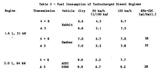
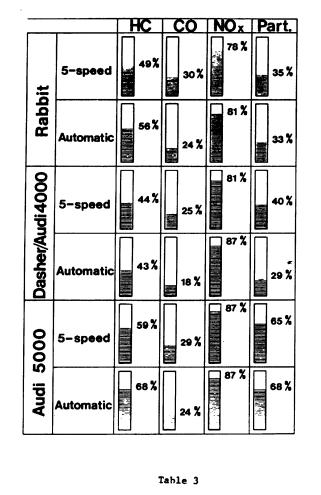
Table 3 gives the summary of the relative exhaust emissions from the city driving cycle where the emission standard is set equal to 100 %. In Table 3 an unburned hydrocarbon limit of 0.41 g/mi, a carbon monoxide limit of 3.4 g/mi and a particulate standard of 0.6 g/mi are used for reference. In regard to the nitric oxide emissions a waiver has been granted for modal year 1982 which allows NOx levels of 1.3 g/mi for VW-Rabbit, 1.4 g/mi for VW-Dasher/AUDI 4000 and 1.5 g/mi for AUDI 5000 vehicles. One can see from Table 3 that in view of hydrocarbon, carbon monoxide and particulate emissions a relatively high margin has been obtained. Only with regard to NOx emissions, last but not least because of their high priority for minimum fuel consumption, are the measured figures relatively higher.
The authors like to thank P. Hofbauer, Executive Director for Aggregate Development, for the guidance provided throughout the project. The authors also like to acknowledge the work of the entire development team. Significant contributions were made from various design and development departments which are headed by P. M. Deja, H. A. Kuck, D. Neyer, K. Sator, U. Sturzebecher and P, Thauer.
[Return to Table of Contents]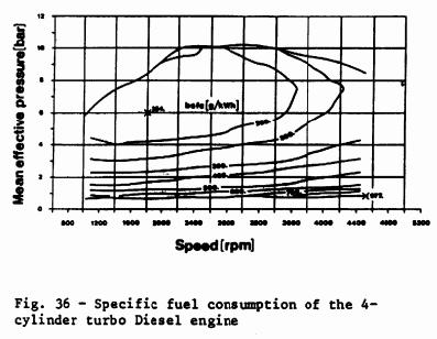