Diagnostic Trouble Codes and Possible Causes
Original author: Jim Brink
Edited and updated by: Roger Brown
Contents:
[return to the Cheap Tricks main page]
Introduction:
All Toyota vehicles with electronic fuel injection utilize the Toyota EFI or TCCS engine management system. This system incorporates many features to enhance performance, emissions, and drive-ability. One feature is the Self Diagnostic System. The self diagnostic system monitors engine operations and when a particular sensor or input varies out of specified operating parameters, the "Check Engine" will be illuminated.
The check engine lamp alerts the driver or technician that a problem exists in the EFI/TCCS ECU or Engine Control Unit or "computer." When the check engine light is illuminated, it is indicating that a problem in the engine management system has been detected. At this time, a "code" may be stored in the ECU which pinpoints a possible component in the EFI/TCCS system. By checking the trouble codes, a possible problem could be narrowed down to a number of causes. While not an exact diagnostic tool, the check engine light and self-diagnostic system can get the individual working on his/her truck close to a possible fault, and, hopefully, to a successful repair.
Listed below are one and two digit trouble codes for the EFI/TCCS systems and possible causes. As mentioned above, this is not an exact science. Many other component failures can cause similar symptoms that can "mask" the actual cause. EFI/TCCS computer interrogation is one of the last steps to engine diagnostics. A thorough inspection of the simple items should be done prior to any computer-related repairs. Sometimes it's the simple things that will get you. In addition, use caution when working on the electrical system of your vehicle. Not only is the electrical system delicate to water, static electricity, and outright physical abuse, the ignition system puts out high voltage as well and you can be seriously injured if you do not exercise basic safety.
Reading the Trouble Codes:
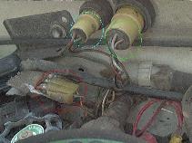
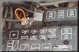
Reading the diagnostic trouble codes is very easy. You will need a paper clip to short the check connectors of the diagnostic connector. The diagnostic connector comes in two types. The early system is located on the inner-left fender well and is a round, green connector, usually located near the air cleaner. Simply jump the two terminals in this connector with the ignition switch in the "ON" position and the engine off. Later models, '87 and newer use a multiple terminal "DIAGNOSTIC" connector which is a small, rectangular-shaped gray "box", usually located near the right fender in the engine compartment. To get codes out of this type of connector, jump the "TE" and "E1" or "TE1" and "E1" terminals. Finding these terminals is easy as the inside cover of the diagnostic connector contains a schematic of the connector pin-outs. If the under hood emission decal (VECI) is still intact on your vehicle, the proper pins for this are outlined there as well.
 |
 |
| Early model EFI Diagnostic Connectors TE-E1 is circled in light blue |
Later-model EFI/TCCS Diagnostic Connector |
The trouble codes will appear as flashes of the check engine lamp. Be sure the ignition key is on, the engine off, and your foot off of the accelerator when reading the codes.
- On the early 22RE engines ('85-'87), there are only "one-digit" codes, that is the entire code will be counted out in 1 - 13 flashes.
-
Later model 22RE engines ('88-'95) can have two different code types
may appear:
-
One-digit and two digit.
- One digit codes have an approximate 4.5 second delay between flashes with the check engine light illuminating for about a half of a second.
- Two digit codes have a 2.5 second delay between them.
-
For example a code two flashes the check engine lamp two times in a
little over one second: I I.
- If two single digit codes are stored, such as a code two and a code four, the lamp may flash as such: ....I I....I I I I. Crude examples but you get the idea.
-
Two digit codes are similar but will flash the lamp with the first
number first and the second number last.
- An example of a code twelve is I ....II and a code twenty four is I I..IIII.
-
One-digit and two digit.
Trouble Codes and Possible Causes:
In reading the trouble code descriptions and probable causes, the most likely causes are listed first followed by less likely causes. So, you'll see "Defective ECU" listed in many codes as a probable cause. SInce it is listed last, it is the least likely cause of any of the problems. So don't assume that if you have a couple of codes that all list "Defective ECU" as a probable cause, that you have a defective ECU. Sure it is possible, but if things basically work aside from the store trouble code, your ECU is probably OK. And don't forget how the various sensors are wired up. You'll have the sensor, possibly with some wires coming off it, that in turn connects to the engine wiring harness. That is where most folks think of looking for "open" or "short" circuits. But those wires also run all the way back to the ECU where they plug in with one of the 3 large connectors. So don't forget the other end of those wires.
Early 22RE engines:
| CODE | DESCRIPTION / PROBABLE CAUSE(S) |
| 1 | Normal operation (no code stored) |
| 2 | Open or shorted Air Flow Meter (AFM) circuit - Defective AFM - Defective Electronic Control Unit (ECU) |
| 3 | No signal from igniter 4 times in succession - Defective Igniter - Defective Main Relay circuit - Defective ECU |
| 4 | Open or shorted Water Thermo Sensor (THW) circuit - Defective THW - Defective ECU |
| 5 | Open or shorted Oxygen Sensor (O2) circuit - Lean or rich indication (with injectors full rich or full lean) - Defective O2 sensor - Defective ECU |
| 6 | No engine revolution sensor (Ne) signal to ECU - Ne being over 1000 RPM in spite of no Ne signal to ECU - Defective Igniter circuit - Defective Igniter - Defective distributor - Defective ECU |
| 7 | Open or shorted Throttle Position Sensor (TPS) circuit - Defective TPS - Defective ECU |
| 8 | Open or shorter Air Thermo Sensor citcuit - Defective intake air thermo sensor circuit (see AFM) - Defective ECU |
| 9 | not used? |
| 10 | No starter switch signal for ECU w/ vehicle speed = 0 and
engine RPM > 800 - Defective Vehicle Speed Sensor (VSS) - Defecticve main relay circuit - Defecticve igniter switch to starter circuit - Defective ECU |
| 11 | Short circuit in Check Connector T with A/C switch ON or
TPS - IDL point OFF - Defective A/C switch - Defective TPS circuit - Defective TPS - Defective ECU |
| 12 | Knock control Sensor (KS) signal has not reached judgement
level in succession - Defective KS circuit - Defective KS - Defective ECU |
| 13 | Knock CPU (Sensor?) faulty |
Some possible causes of the above trouble codes:
-
Codse 3 and 6 point to the coil and ignitor, try a new one.
- Another symptom is an erratic fatory tachometer, as the tach. signal comes from the ignitor circuit.
-
Any of the TPS codes; test out the Throttle
Position Sensor both at the sensor and at the ECU connector,
- Also make sure the TPS connector is tight.
-
Any of the AFM codes; test out the Air
Flow Meter both at the sensor and at the ECU connector,
- Also make sure the AFM connector is tight.
- Any of the Knock Sensor codes; check the connector and wiring at the Knock Sensor, it is a shielded wire and is somewhat delicate.
Later 22RE engines:
| ONE-DIGIT | TWO-DIGIT | POSSIBLE CAUSE OF CODE/SYMPTOM |
1 |
NONE |
SYSTEM NORMAL |
-- |
11 |
LOSS OF POWER SUPPLY TO ECU --IGNITION SWITCH/CIRCUIT --MAIN RELAY/CIRCUIT --ECU |
| 6 | 12 | RPM SIGNAL-NO SIGNAL TO ECU FROM DISTRIBUTOR ("Ne" OR "G") AFTER ENGINE HAS BEEN CRANKED --DISTRIBUTOR/CIRCUIT --STARTER SIGNAL CIRCUIT --IGNITER/IGNITER CIRCUIT --ECU |
-- |
13 |
SAME AS ABOVE BUT AFTER ENGINE HAS RUN AT 1,000-1,500 RPM --DISTRIBUTOR/DISTRIBUTOR CIRCUIT --ECU |
3 |
14 |
IGNITION SIGNAL--NO "IGF" SIGNAL TO ECU --IGNITER/IGNITER CIRCUIT --IGNITER AND IGNITION COIL/CIRCUIT --ECU |
5 |
21 |
OXYGEN SENSOR SIGNAL/OXYGEN SENSOR HEATER SIGNAL OPEN OR SHORT IN OXYGEN SENSOR OR OXYGEN SENSOR SIGNAL |
4 |
22 |
WATER TEMPERATURE SENSOR SIGNAL--OPEN OR SHORT IN WATER TEMP. SENSOR SIGNAL --WATER TEMPERATURE SENSOR CIRCUIT --WATER TEMPERATURE SENSOR --ECU |
8 |
24 |
INTAKE AIR TEMPERATURE SENSOR SIGNAL--OPEN OR SHORT IN INTAKE AIR TEMP. SIGNAL --INTAKE AIR TEMPERATURE CIRCUIT --INTAKE AIR TEMPERATURE SENSOR --ECU |
-- |
25 |
AIR/FUEL RATIO LEAN INDICATOR--LEAN SIGNAL SENT TO ECU FROM O2 SENSOR --INJECTOR FAULT(S) --FUEL PRESSURE --OXYGEN SENSOR --AIRFLOW METER OR MAP SENSOR --IGNITION --ECU |
-- |
26 |
AIR/FUEL RATIO RICH INDICATOR --SAME AS ABOVE --COLD START INJECTOR |
-- |
27 |
SUB-OXYGEN SENSOR CIRCUIT OR SUB-OXYGEN SENSOR HEATER CIRCUIT --SUB OXYGEN SENSOR/HEATER/CIRCUIT --ECU |
-- |
28 |
No.2 OXYGEN SENSOR/OXYGEN SENSOR HEATER --SAME AS CODE 21 |
2 |
31 |
MANIFOLD AND/OR AIRFLOW METER SENSOR SIGNAL CIRCUIT --AIRFLOW METER/CIRCUIT --MANIFOLD PRESSURE SENSOR/CIRCUIT --ECU |
-- |
32 |
AIRFLOW METER SIGNAL (VANE-TYPE) --AIRFLOW METER./CIRCUIT --ECU |
14 |
34 |
TURBOCHARGER PRESSURE--ABNORMAL TURBOCHARGER PRESSURE --TURBO CHARGER --AIRFLOW METER/MANIFOLD/TURBOCHARGER PRESSURE SENSOR --INTERCOOLER SYSTEM --ECU |
-- |
35 |
TURBOCHARGER PRESSURE SENSOR SIGNAL --TURBOCHARGER PRESSURE SENSOR --ECU |
7 |
41 |
THROTTLE POSITION SENSOR SIGNAL--OPEN OR SHORT IN TPS SIGNAL --TPS SENSOR --TPS SIGNAL/CIRCUIT --ECU |
9 |
42 |
VEHICLE SPEED SENSOR SIGNAL CIRCUIT--NO SPD. SIGNAL FOR SEVERAL SECONDS WHILE VEHICLE IS OPERATED UNDER HEAVY LOAD (TPS/MAP/AIR FLOW INPUTS) --SPEED SENSOR/CIRCUIT --ECU |
10 |
43 |
STARTER SIGNAL--NO "STA" SIGNAL TO ECU UNTIL ENGINE SPEED EXCEEDS 800RPM --IGNITION SWITCH/CIRCUIT --ECU |
11 |
51 |
SWITCH SIGNALS IDL (tps) CONTACTS OFF, NEUTRAL START SWITCH OFF, A/C SWITCH "ON" SIGNAL TO ECU WITH DIAGNOSTIC CHECK CONNECTOR SHORTED --A/C SWITCH/CIRCUIT --A/C AMPLIFIER --TPS/CIRCUIT --NEUTRAL START SWITCH/CIRCUIT --ECU |
12 |
52 |
KNOCK SENSOR SIGNAL--OPEN OR SHORT IN KNOCK SENSOR SIGNAL --KNOCK SENSOR/CIRCUIT ECU |
13 |
53 |
KNOCK CONTROL SIGNAL IN ECU --ECU |
-- |
71 |
EGR VALVE MALFUNCTION--EXHAUST GAS TEMPERATURE BELOW SPEC. FOR EGR CONTROL --EGR SYSTEM --EGR GAS TEMPERATURE SENSOR/CIRCUIT |
- - |
72 |
AIR CONDITIONER COMPRESSOR RELAY/RELAY SIGNAL --A/C COMPRESSOR RELAY/CIRCUIT --ECU |
While a lot of the possible faults in the EFI system point to the ECU itself, it should be noted that ECU failure is not common. The ECU should be replaced only as a last resort or if all diagnoses points to a bad ECU. Usually, troublesome EFI problems are a result of poor grounds, shorted wiring, and bad connections at sensors.When all else fails, carefully consult your factory repair manual. It contains more comprehensive diagnostic information and great electrical wiring diagrams.
Happy "Diagnosticating!"
Jim Brink - Toyota/ASE Certified Master Automotive Technician
Visitor # 319108 since 28.AUG.2010
[Last updated: 30.March.2022 ]