Toyota 4Runner and Pickup: Cheap Tricks
"Real Wheelers Are Built, Not Bought"
Here are some cheap tricks and tips I've found for repairing and upgrading my rig. These are simple modifications and repairs that for the most part cost very little and take little time.
Contents:
- Low cost modifications
- Not so low cost modifications
- Tips and Techniques
- Troubleshooting and Repairs
MODIFICATION$:
-
 DIY: EGR and Air Injection "Gaskets".
- Click on the linked photo to bring up the information and take note of the end as you don't want to forget to make the holes in the "gaskets" because that might block off the exhaust gas flow :)
-
LED light bulb upgrades
-
 Brighter Headlights
-
Here are some engine photos of
the 22REC engine taken over the years...
- Here's how to bypass the VSV that connects to the Fuel Pressure Regulator (FPR)
- See photos 8, 9 and 10 for the entire process...
- Deck Light Mod
- Cooler and Safer Oil
- Waterproofing ideas
- Hawse Fairlead for winch bumper
- Key Release button
- Clinometer tweaks
- Easy mount Kayline Soft Top and other soft top options for 1st gen. 4Runner
- Bulletproof your motor mounts
- Got more gauges than dash? Add a custom gauge pillar
- Continuous Wheel Balancers
- Stripe Removal
-
Rear Window Tips and Repairs
- Steering Stabilizer Removal
- Power windows w/o the key in the ignition
- CB Antenna Mounting
- A Cheap Body Lift
- Quick disconnect mud flaps
- Auxiliary Power (and more)
- Driver's side grab handle
- Relocated tailpipe
- Seat Lift
- Front sway bar quick disconnects
- Combined Turn/Parking lights
- Custom front valence replacement
MODIFICATION$$$:
-
Toyota Axle Modifications
- Drive-train and gas tank Lift
- 22RE - Engine Modifications
- Cross-Over/HySteer Steering
- On-Board Welder
- Dual battery installation
- Hot Water Shower system
- On-board air compressor
- Electric Radiator Fan and Custom Controls
- 4Runner bumper upgrades
- 4Runner suspension upgrades
TIPS AND TECHNIQUES:
- New gear break-in
- Driveshaft/Drive-line (aka Propeller Shaft) Basics
- Tire Siping for added traction
- Suspension test ramp
- Marlin Crawler tips and tricks
- What is this Banana Scale?
TROUBLESHOOTING and REPAIRS:
-
Bizzare Idle with brakes applied
-
Easy starter repairs, now available on-line:
starter solenoid contacts
-
Power Antenna Repair
- Radiator Fan Clutch Repair (aka Fluid Coupling)
- Windshield Trim Replacement
- Pinion Seal Replacement
- 4Runner B-pillar trim removal/repair
- Replacing damaged door handle trim
-
Repairing defectivepower window switch
- 22R/RE/RET Timing Chain Replacement Procedure
- TPS (Throttle Position Sensor) Testing and Adjustment
- AFM (Air Flow Meter) Testing
- Timing and Diagnostic Check Connector locations
- Alternator:
- Repairing defective blower motors
- Headlight_Combo Switch Repair
- Have problems with overheating when your heater is on?
- Solid Axle Rebuild
-
Rear Window Repairs / Modifications
- Replacing those pesky light bulbs in the dash board
- Re-upholstering center console
![]()
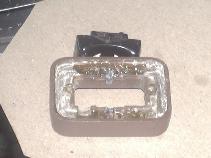
Deck Light Mod:
You know, it is that tiny light behind the factory roll bar on the driver's side, that doesn't seem to work. Took me a while to figure out that you needed to have the parking lights on (it is fed from the main exterior light relay). Kind of useless though, for example if you are camping or sleeping in back and need some light, you have to run around to the front, turn on the parking lights, all to have a puny 3W light in back. Add to that the the deck light is essentially "on the deck", so if you have anything in back, the light will likely be blocked. The only cool thing about the deck light is that it has both front and rear switches, wired up like you would have in a hallway with a switch at each end. Turn the light on with one switch, walk down the hall and turn the light off with the other switch.
So, while this deck light is sort of lame, it has promise. First step is to re-power it off the battery. Pull the lower dash off, disconnect the deck light plug and find the dark green wire (upper left of the connector) - that supplies power to the whole circuit. I cut it, spliced in a male and female spade connector and then tapped into my CB radio power feed. Any source of power could be used, the dome light fuse that powers the dome light is right there in the fuse block. I left the old wire with a mating spade connector in case I ever wanted to revert to stock.
Then, since the light may now actually get used, I replaced the 31mm festoon bulb with a white, 6-LED festoon bulb replacement. This LED puts out more light than the 3W incandescent bulb with 1/4 the current draw (about 60mA). So now there is light available any time, controllable from the front or rear switch. However, one big problem remains, the light is usually blocked with gear in the bed.
So, to address this problem, a different light location is needed. I already have a 12V LED trouble light stick zip tied to the roll bar. It has a 12V plug on it and I have 3 - 12V outlets down the passenger side of the bed rail that I can plug it into when needed. It throws a whole lot of light but it is sometimes inconvenient fumbling around in the dark trying to find the plug and an empty socket to stick it into. So the final solution is to add a switched 12V outlet on the driver's side, right above the deck light, power is tapped off the deck light. This allows the overhead light to be left plugged in all the time and switched on and off with a switch. And the overhead light also doubles as a trouble light, it can be easily unplugged and removed. Being a solid state light, it does not suffer from banging around like a fluorescent light does (I killed a few of those over the years). And the LEDs are very efficient light producers, so no worries about leaving them on for hours at a time while camping.
 |
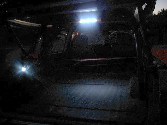 |
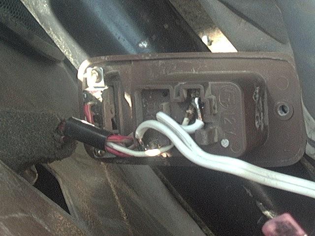
| Wiring Detail | Side and Overhead Lights |
In the above-left image, the connections of the wires to the back of the deck light socket is shown. With LED lights, polarity matters, the R-B wire is +12V and the W-B wire is ground. The two wires are run up to a 12V outlet screwed to the side of the bed rail. The LED trouble light plugs into that outlet and can then be turned on (image above-right) or off from either the switch at the deck light or from the deck light switch on the dash. As wired, even the indicator light on the front deck light switch illuminates so you don't forget to leave it on. The lit image above does not do the light output justice (my old digital camera did poorly in low light), but suffice it to say, reading would not be a problem with the amount of light thrown by the overhead LEDs. Also, the trouble light has an on/off switch so it can be shut off to use only the deck light. With the 60 bright LEDs in the trouble light, it does pull a few amps of current, but it puts out about the same light as a 100W incandescent bulb. Unfortunately, that LED trouble light didn't last very long.
More information:
- Installed new overhead lighting
- A ways down this photo album is an update to my deck light
- New housing to relocate the deck light
-
Replacement deck light lens
[back to the top]

Replacing damaged door handle trim:
After 19 years of California sun, I found the upper edges of the trim rings around the inside door handles were badly damaged by the UV light. The plastic was cracking and chunks were starting to fall off. Attempts to use vinyl cleaners and treatments met with no success. Then it dawned on me that the trim on the passenger side was a perfect fit for the driver side. Swapping the two trim rings placed the sun-damaged side down and the like-new side up, giving a nice face lift to the look of the doors. Cost nothing, perfect color match and hopefully it'll last another 19 years!
And here is a followup solution that has been working well.
[back to the top]4Runner B-pillar trim removal/repair:
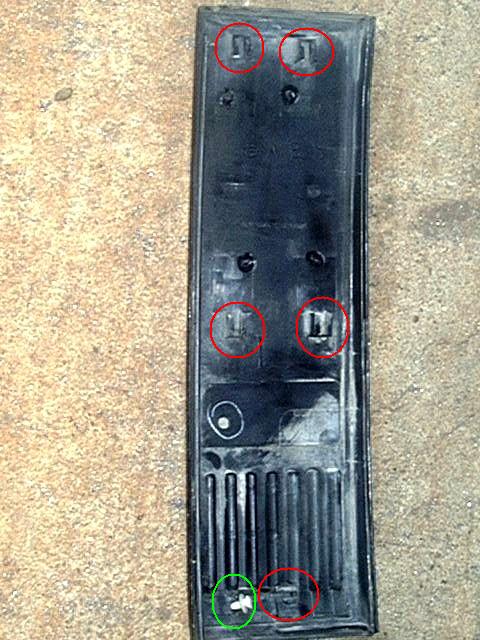
On the 1st generation 4Runner, there is a plastic trim panel located on the B-pillar, just behind the front doors. One day I decided to see how that piece was held in place, as it seemed to have no visible fasteners.
As you can see image "A" below, there are 5 slots (circled in red) and one of several white plastic pins (circled in green). The upper 4 slots are vertical and the bottom one is horizontal. This is the key to removing (and re-installing the trim panel). What you need to do is to push the bottom rear of the panel forward to slide the bottom pin out of the bottom slot. Then you ideally would push the panel up to release the 4 upper pins from the slots. What I found on my '85 was that the drip edge where the B-pillar meets the roof panel stopped the side trim piece from sliding up high enough to clear the pins. So I pushed it up as high as I could and then pulled the bottom of the panel away from the body until the clips popped out of the slots. If you do this carefully enough, the pins and slots will not get damaged too much.
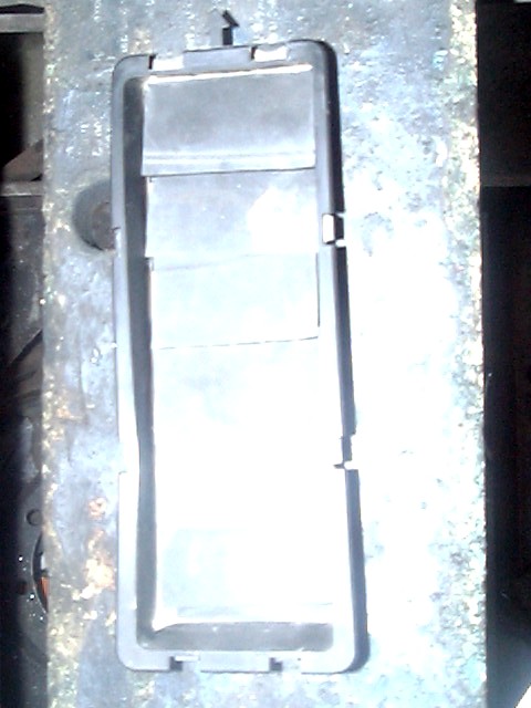
A: B-pillar Trim B: B-pillar trim removed C: B-pillar vent Once the trim piece is off, you'll be able to remove the 5 pins that are pressed into the 5 holes visible in image "B" above. Under that trim panel is a small vent in the lower part of the B-pillar. In mine, I found little shriveled up pieces of what looked like rubber or vinyl that once formed little flaps over the vent openings. So I found an old inner tube and cut 6 new little flaps for each side (there are vents on both sides) and the glued the flaps to the back side of the vent, shown in detail in image "C". I guess the idea is the flaps cover the vent to keep out water and dirt that may be behind the trim panel, but yet allow air to get pulled out of the vehicle while driving.
To replace the trim panel, I found that if I lightly glued the upper 4 pins into the slots (to hold them in place) and then inserting the lower pin into the body, I could line up the 4 upper pins int he 4 body holes and press the panel into place. Then engage the lower pin by pulling the panel back into position.
[back to the top]Oil Cooler:
There are a few options for adding oil coolers to an engine. Most require adding an adapter to the oil filter then running hoses to and from an air-oil or water-oil heat exchanger located elsewhere. I found a simpler version that seems to work well to add a bit of cooling effect to the oil filter and also helps protect it from flying road debris:
I used the Cool Collar from JC Whitney to fit over the oil filter, a finned aluminum extrusion held in place with a hose clamp. The regular size exactly fits the stock 22RE oil filter. I took the time to go around the sharp fin corners on the end of the cooler with a set of wire cutters to trim off the sharp ends and also filed them smooth to avoid nasty scrapes in the future. I find the fins make it easy to grip the filter for installation and removal. It just takes a few seconds to move it to the new filter at each oil change. I also added the same filter cooler to my Howe power steering fluid reservoir filter.
[back to the top]Fuel Pump Tricks:
Here are a few handy tips and tricks for working on the high pressure EFI fuel pumps on Toyota 22RE/22RET and V6 (3VZE) trucks.
Easy Fuel Pump Access:
In the 1st generation Toyota 4Runner, there is a handy access hatch under the rear seat cushions. Remove the screws that hold it in place and the fuel pump is easily accessible. It is held in with some screws and you can remove and replace it without draining and dropping the gas tank.
Fuel Pump Test Jumper:
If you find your engine is hard to start when it has been sitting for a while, but is still warm, you might have a problem with the fuel pump not turning on. I noticed my '85 4Runner would need to be cranked for many seconds before it would start. When I was doing some work on the engine, I decided to install an electronic fuel pressure gauge with a sender in the fuel injector rail. I drilled and tapped a hole in the end of the rail, soldered in a brass pipe elbow (1/8"-1/4" street elbow) and screwed the sender into that. That is when I noticed when the engine is cranking but not starting, my fuel pressure was zero. Then, the fuel pressure would pop up to the normal operating range and the engine would fire. I reasoned that I had to crank the engine fast enough to pull sufficient air into the AFM to trip the fuel pump contacts and pressurize the system (I suspect I have an air leak in the fuel system that is letting the residual pressure bleed off over a few minutes - I see no fuel leaking). Anyway, digging through the handy FSM, I found the following (Fuel Pump Check Connector):
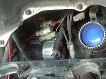
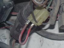
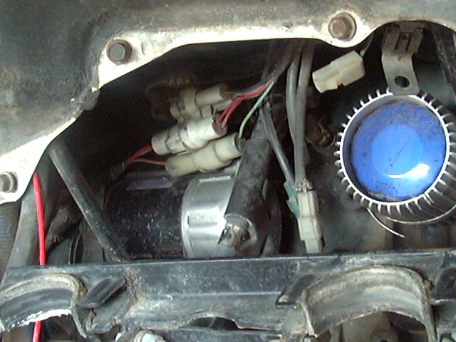
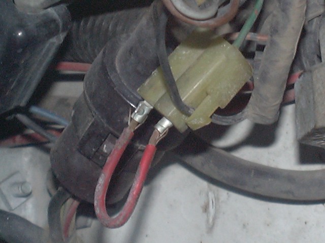
I first found this while going through the engine check out procedure after doing a rebuild procedure, but then it dawned on me that this would help with the starting fuel pressure problem. So I stuck a wire in the check connector (its the rectangular connector just left of center in image A below - circled in red). FYI. That photo was taken looking at the driver's side inner fender, under the hood from the passenger side, for reference. Image B shows a closeup of the RED jumper wire inserted into the test connector, a pair of spade lugs are crimped onto the ends of the wire and its just inserted into the connector terminals (see image A below).
And viola, the engine starts on the first crank almost all the time, hot, cold, no difference. The fuel pump switch in my AFM tests out fine, so I don't think that is the cause of my problem. I imagine this is sort of a safety feature, shuts off the fuel pump if the engine stops. With the jumper installed, the fuel pump runs whenever the ignition is on.
When does the fuel pump run?
- When the key in the ignition switch is in the START position (via the ECA STA signal wire)
- When the engine is running (key in ON position) and pulling air through the Air Flow Meter (AFM) causing the AFM-Fc contact to close
-
Or when the key is ON and the Fuel Pump (FP) test jumper is installed
- Note: If the FP jumper is absent, the fuel pump DOES NOT run if the engine is not running and the key is ON
So what is this "cheap trick"good for?
- If you have the above mentioned problem while starting, this will ensure the fuel pump is running when the starter is operating.
- If you suspect problems with your Air Flow Meter's fuel pump contact, this jumper will bypass the AFM's fuel pump contact, too.
- And finally, if you need to check for fuel-related problems like leaks, pressure, etc. with the engine not running, this is what this feature was designed for in the first place.
- Note, this should work on the 2.4/4 and 3.0/V6 engines, but it does not work on the newer 2.7/4 and 3.4/V6 engines.
If you find this jumper fixes your starting problem, what does this tell you?
- First off your fuel pump is OK.
- The wiring to the fuel pump is OK
- The circuit opening (CO) relay is functioning to some degree (i.e. the test jumper is making it turn on and send power to the fuel pump)
So what might be the problem?
- It might be that the Circuit Opening Relay secondary coil is weak or defective or the STA signal that turns on that relay is weak.
- If you want to pull it out to test it, here is where it is located and how to test it.
Note that the Main Relay is located in the driver's side kick panel, in the lower left hand corner of the relay panel above the fuse block.
Troubleshooting tips (if the above tips don't help):
- So if you are not getting power to the fuel pump with the test jumper and the CO relay seems to be working OK, you'll need to dig out a volt meter and start troubleshooting.
- Many people will look at the above diagram and instantly jump to fusible links, EFI fuse or Main Relay as the likely source of the problem. But truth be told, if those are out, the engine cranking and not starting is likely to be the least of your worries, as everything will be dead.
- Rather, you want to start at the end of the circuit (i.e. the fuel pump) and work backwards to the battery, testing points in between and based upon those test results, either eliminate the components "down stream" (that is towards the fuel pump) as OK or as bad.
-
So the idea is you have no power at the fuel pump and you have good
power at the battery (assuming your battery is not dead). Well, at some
place in between there must be a problem. So pick some point about half
way between the pump and battery and test the voltage there.
- If the voltage at your test point is OK, then everything "up stream" (i.e. between there and the battery) is OK and the problem lies down stream, so pick a new test point mid-way between this point and the pump.
- If the voltage at your test point is bad, then the problem lies up stream from the test point, so pick a new test point mid-way between this point and the battery.
- The repeat your test and this new test point and keep going until you narrow down the source of the problem.
- The idea is to "divide and conquer" the circuit. So for example, if you have say 8 "things" (like fuses, relays, wires, connectors) in a circuit with power at one end and no power at the other end, if you go to the mid-point and test for voltage, you will basically be eliminating 4 of those "things"with the first test. Then by dividing those 4 suspect "things" in half, leaving only 2. Then repeat once more and you divide those 2 suspect "things" in half, leaving 1 "thing" left, and pretty much by the process of elimination the one "thing" with power on one side and no power on the other side is the cause of the problem.
So, you might ask if I ever found the cause of my hard starting issue? Well, the answer would be no. I actually ran with a switch on the check connector for some time, then one day the system was back to working normally. It has never acted up since that time, so with no problems, there is nothing to fix.
IMPORTANT:
Running with the check jumper installed is not ideal as it defeats a safety feature built into that system. Normally, if the engine ever stops running, so will the fuel pump. If you have the jumper installed, the fuel pump will run any time the key is in the ON position, engine running or not. So when might this matter? If you run out of gas, the engine will stop and so will the fuel pump, this avoids damage to the fuel pump since it relies on the gasoline to cool and lubricate it. Leave the pump running dry and it will fail quickly. The other more serious issue would be in the event of a crash where you might have a damage to a fuel line. If the pump were to stay running, it would cause more gas to leak out under pressure, increasing the risk of fire. So best not to run with the jumper in place. I recall my old '78 VW Rabbit (CIS fuel injection) was set up from the factory that the fuel pump kicked on with ignition. I think all the FWD VWs (A1 platofrm) up though '84 were like this.
To get arounhd this, you could connect the test jumper up to a momentary switch on the dash. The hold that button down while starting then release the button once the engine is running normally. Or you could troubleshoot the cause of the starting problem and fix it.
[back to the top]Timing and Diagnostic Check Connector location(s)
These are located on the driver's side inner fender on the earlier EFI trucks and 4Runners, later models had an integrated diagnostics box located on the passenger side of the engine bay, near the fuse box.
-
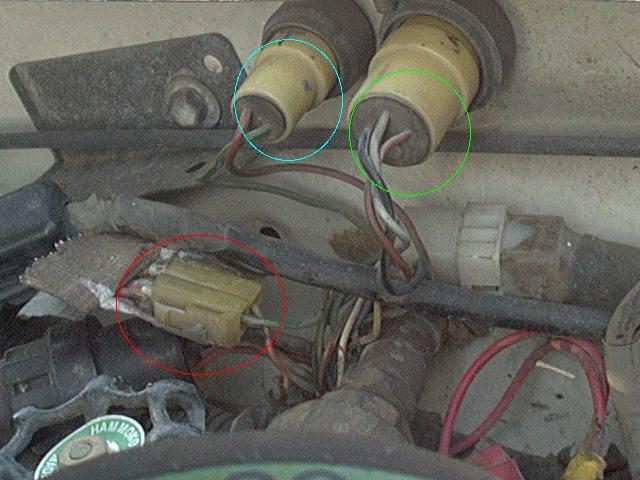
The small round connector at the top of the image below is the
notorious "T" connector (location of the T and E1 terminals)
for setting timing and checking ECU codes (circled
in light blue):
- On the 22RE, ignition timing is specified at 5°BTDC with the above jumper installed and the idle speed set to around 750 RPM.
- The larger round connector is some other test plug (circled in green) has the ECU O2 circuit test voltages, such as the Vf signal.
- There is also a small round one-wire connector (not shown in the pictures below, mine has a black rubber cap) that has the O2 sensor voltage for testing purposes.
A: Overview of early engine
Diagnostic and Test ConnectorsB: Early model Fuel Pump Test
Connector w/ jumper installed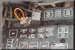
C: Later model TCCS Diagnostic Connector
(orange wire plugged into it)D: Later model box w/ Fuel Pump
(FP-B+) Test Jumper installed
.If anyone has a photo of this, send it in. E: TCCS Diagnostic/Timing Jumper
(E1-TE1) terminal locationsF: [Click above thumbnails for a larger image]
Note: On later model trucks, there is no separate fuel pump test connector, rather you have to use the diagnostic test connector (shown in photo C above) and follow the test procedure outlined in the Factory Service Manual, which involves placing a jumper wire between the "Fp" and "B+" terminals (see photo D). The Timing/Diagnostic jumper terminals (E1 - TE1) are shown in photo E.
The underlying problem is most likely that the winding on the circuit opening relay (see schematic above) that is energized by the ECU STArt signal is not working properly. Lacking this signal to energize the fuel pump, I get no fuel pressure while starting, until enough air flows through the AFM to trip its fuel pump contact. I hope to get the CO relay checked out and hopefully this will correct the problem.
You'll then need to buy or build a code reading/scan tool for the ECU. While you may find a down-right dearth of such tools available for the early (pre-ODBII) Toyota ECUs, many office supply stores do carry "scan tools" :)

Basic Scan Tool Improved Scan Tool Hint: The metal ones work the best!
Assembly and Use Instructions for basic Scan Tool:
- Simply unfold the Scan Tool.
-
Precisely bend the legs to match the spacing of the diagnostic
connector terminals.
- Early engines label them T and E1, later models may list them as T and TE1.
- Shove it in.
- Then turn on the ignition (but do not start the engine)
- Read the flashing code(s) on the Check Engine light.
For the improved Scan Tool, use a pair of bare spade lugs crimped onto a short length of wire. Thicker and/or solid core wire will make a better jumper, less likely to bend in insertion. You may need to cut or file down the width of the spade lugs to fit the diagnostic port terminals. If you search for the official Toyota SST 09843-18020 (or 09843-18040), you'll see it has narrow flat ends.
On my '85, I took the 2 spade lugs, connected to 2 wires and ran those to a toggle switch I added to the fender. Flip that switch on and I can read CEL codes or set the engine timing.
Notes:
-
Once you have found the diagnostic test connector, just insert a short
piece of wire or even a bent paper clip into the contacts and turn the
engine on (do not start it) and read the code(s) by counting the
flashes of the Check Engine light as noted:
- For the 1985 and similar 22RE engines, this chart has the codes for the earlier ECUs (typically '85-'87)
- Here is a chart for the 1988 through 1995 pickups and 4Runners
- A sharp eye may spot a mysterious round valve handle in the lower left corner of the picture above. If interested in what that is, you can find out more on this page.
The Circuit Opening relay is located in the passenger side kick panel/A-pillar area.
This is what the CO relay and connector/socket looks like (notice it is labeled as Circuit Opening Relay):
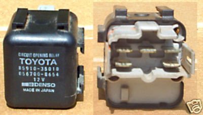
Typical Circuit Opening Relay - It may be located behind/above the ECU module, behind/beside the passenger front speaker.
-
It is a small black box, about 2" square, likely need to pull the
glove box to reach in from above.
- Also back there are the headlight reminder module (black box) and the wiper control module (green box).
-
It is a fairly expensive part and is likely only available from Toyota
or used from a junkyard or eBay for example.
- http://personal.utulsa.edu/~nathan-buchanan/93fsm/engine/38circuito.pdf It is not just a simple relay, thus the high cost. It is more like 2 relays in one, there are two separate coils and one set of contacts.
- The CO relay kind of functions like a logical OR gate, if power is applied to one OR the other relay coil, it turns on. So the one coil is used when the starter is running (and the engine is not) and the other one is on when the engine is running and the incoming air opens the vane in the Air Flow Meter and that closes the AFM/Fp contact.
Testing the CO relay is basically like testing a regular relay, just a little more complicated by the extra coil and the different readings for each. Here is the FSM page for testing the AFM on later model engines, should be quite similar to the tests on the earlier relays:
-
To check the CO relay there are a few simple tests that can be done:
- Either disconnect the small wire to the starter solenoid or install the fuel pump test jumper, then turn the ignition key to the Start or Run position respectively and listen for the CO relay closing and opening with a loud click.
- You can test for ~12 volts at the Fp terminal of the relay socket while starting or running the engine .
- If problems suspected, test the relay resistances (relay removed from socket) as follows:
Pin 1 Pin 2 Ohms Relay STA E1 17-25 n/a +B Fc 88-132 n/w +B Fp Infinite/open circuit Off +B Fp 0/Short circuit On So the above ohm meter tests are of course done at no load and no power being applied to the relay. They will tell if the relay is dead (burned out coil or contacts), but will not tell you that the relay is 100% operational. The relay terminals may be identified with the table below.
CO Relay Pins/Wire Colors Fc/Grn n/c E1/W-B Fp/L.Bl +B/Blk STA/B-W What the above table shows is a representation of the CO Relay socket, it'll have 5 pins and note the table is rotated 180° with respect to the picture above:
- The upper left pin is the Fc terminal and is connected to the Green wire
- The upper right pin is the E1 terminal and has a White w/ Black stripe wire
- The lower left pin is the Fp terminal and has a Light Blue wire
- The lower middle pin is the +B terminal and has a Black wire
- The lower right pin is the STA terminal and has a Black w/ White stripe wire
To do that, you need to test it in the vehicle, under power and with a load (i.e. the fuel pump) applied.
- To do these type of tests, you'll need a volt meter and some way to probe the connections to and from the relay with it installed in it's socket.
-
And you can either install the fuel pump test jumper (on earlier
vehicles) and turn on the ignition.
- Or you can disconnect the starter solenoid (small) wire and turn the key to Start.
- The other test mode is to manually open the vane in the Air Flow Meter (AFM) and have the ignition on.
- Since both while starting and while the AFM vane is open, the CO relay should be energized, so you should do both tests, especially if you are having a problem in one or the other mode.
-
You can also install a jumper across the +B and Fp terminals in the CO
relay socket to send power to fuel pump for testing wiring
- This would of course be with the CO relay removed and you are basically bypassing the relay completely.
- Besides the fuel pump, the CO relay also feeds power to the heater coil in the auxiliary/idle air valve (at least on the earlier 22REs). The coil heats up inside the valve and causes it to close off the extra air used to warm up the engine from a cold start.
So first test is for the incoming voltage. You should see close to the battery voltage at the input (+B) terminal of the CO relay, that is within 0.5 volts, the closer to battery voltage the better. For example, if you measure 12.6 volts at the battery and only 10.0 volts at the CO relay, there is a wiring or component issue with the circuit from the battery to the CO relay. Something is causing that measured (12.6 - 10.0 = 2.6 volts) drop, so find out what is causing that drop and fix it. After all, as the saying goes "Garbage In, garbage Out". If the CO relay can't get enough voltage into it, how can it get enough voltage to the fuel pump? A relay can only pass on the voltage it is given, it can't magically make any higher. So, given a decent input voltage, test the output voltage and use the same reasoning; voltage should be within 0.5 volts of the battery. And finally, you can test the voltage at the fuel pump and again, it should be close to the battery voltage. If not, trace back to find out where the drop is coming from. Now, for example, if you see like 12.4 volts into the CO relay and only 9.6 volts out, there is an issue inside the CO relay, likely burned or dirty contacts that are not making a good electrical connection. You might be able to open the relay and clean the contacts with a small file or you may need to replace the relay.
Note that the CO relay is basically like 2 relays in one. That is it has two windings, either of which can cause the relay to turn on. This is the electro-mechanical equivalent of a logical OR circuit, that is if either input A or input B is on, output C will be on. In CO relay terms, if the Fc contact in the AFM is closed OR the ECU STA signal is active, the Fp output contact will be closed and power will flow to the fuel pump. THis was the Toyota engineer's way of combining the need for the fuel pump to run while starting the engine or while it was running. While the starter is running, STA will be active and turn on the CO relay. Once the engine is running, Fc will be closed in the AFM and that will keep the CO relay turned on. You'll notice this is the reason for the two slightly different test specifications for the two relay windings, one (STA) is designed to be driven by a digital signal from the ECU and the other (Fc) is designed to be run from a contact closure in the AFM. So the STA winding is likely to have additional components associated with it inside the CO relay housing to adapt it for use with the ECU output, since relay coils and solid state circuitry generally don't get along too well due to the voltage spikes that coils (inductors) produce when the are turned on and off for to the changing magnetic fields and the coils wires (remember Maxwell's Law?).
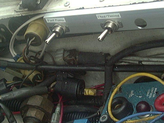
And, after tiring of fumbling around for something to jumper either the diagnostics or fuel pump test connector, I came up with a very simple solution. Using a piece of aluminum angle, pop-riveted to the lip of the fender, I drilled a couple of holes to mount a pair of SPST toggle switches. A pair of wires from each switch runs to the appropriate test plug and now it is a simple matter to flip a switch and pull the diagnostics codes:
Fuel Pump and Diag. Switches - NOTES:
-
The switches are not stock, I ADDED them and the aluminum panel to
mount them on.
- You DO NOT have to do this, I'm merely showing what I DID!
- Also the blue electrical box in the lower right corner is the control box for an on-board welder and that is not stock either.
- I ADDED it.
- Finally note that the blue box is located where the stock 22RE air filter box is located.
- Mine has obviously been moved elsewhere.
- You DO NOT have to do this, I'm merely showing what I DID!
And once you have read out the codes and potentially fixed the problems associated with them and you want to clear the Check Engine Light, how do you do that? Simple, you can either pull the "EFI" fuse in the driver's side kick panel fuse panel, or disconnect the battery (either terminal) for a few minutes. Doing either of these removes power from the ECU and causes it to reset. This both clears any stored codes, but also any stored engine data, so the ECU will need to "re-learn" the fine tuning data for the fuel injection system, which it will do in a few miles of driving.
[back to the top]Hawse Fairlead:
When I installed my front bumper and winch, it came with a roller fairlead. The rollers help guide and protect the winch cable for angled pulls, but I didn't like the fact the the fairlead stuck out so far. I found out there is a different type of fairlead called a Hawse Fairlead. It consists of a piece of steel with a gradual radius formed in its face. The radius serves many of the same purposes as the roller fairlead, but since it is both continuous in all directions and is both smaller and more rugged, this seemed to be a better solution for me.
I ordered a Warn Hawse Fairlead and unfortunately got something that was way too small to fit my bumper, I think it was for an ATV winch. So, I decided to modify the front of my bumper (its made out of 3/8" steel plate) by grinding a radius in the winch cable opening. About 30 minutes with the grinder and I had a nicely rounded hawse fairlead opening. I also welded the nuts for the roller fairlead to the backside of the bumper. Now, I use the integral Hawse fairlead most of the time and in a few minutes can have the roller fairlead attached.
- Cost:
- A bit of grinding wheel
- Rating:
-
 /2
/2
Key Release Button:
The very first thing I disliked about my 4Runner on its test drive before I bought it was that silly button you have to depress to remove the key. I put up with that annoyance for nearly 5 years. One day, I had occasion to open up the steering column housing and figured I'd take a shot at disabling that "feature". Apparently this is only used on certain years of trucks, but I didn't feel up to swapping out an ignition switch from another truck and fool with re-keying everything. There didn't appear to be anyway to remove the button, nor did there seem to be any harm if having it pressed all the time. So I whipped up a bit of epoxy, applied a bit around the base of the button then clamped it down until the glue cured. It helps to depress the button a few times to work the glue down around the button body to give added strength.
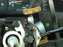
Viola, key can be removed with one hand! Don't overdo the glue, I trimmed off most of the excess once it set up a bit and if need be, can easy twist the button loose. With the housing installed, you can only see the top of the button. Another option at doing this mod is to insert the key into the lock, turn it slightly and depress the release pin (housing removed for access) then you can remove the lock and access the internal mechanism that does the locking. There is a metal piece that is released by the push button that can be removed. But since gluing down the button works well, I did not bother with modifying the ignition switch mechanism.
- Cost:
- A dab of epoxy
- Rating:
-
/2
New Gear Break-in:
You buy a new car and you might hear about how to break in the new engine. There seem to be a few popular engine break-in regimens, but most involve keeping speeds down for the first 500-1000 miles, avoid driving an steady speeds, and change the oil at 1000-2000 miles or so to flush out metal shavings and other contaminants.
So, why is it you never hear about breaking in the transmission or differential gears? I suppose its assumed that if you take at easy breaking in the new engine, the gears and other moving parts will take care of themselves. However, if you change the gears in your 4WD truck that's already well broken in, you should take care and break the gears in properly. After all, you are probably upgrading the gears because you went to larger tires and also do low speed offroad driving, both of which mean there are more stresses on the ring an pinion gears themselves, compared to a passenger car driving on the freeway. Also, ther first thing you are probably going to want to do is lock those hubs and take the rig to the local off-road area and see what it'll do!
So why do gears need a break-in period? When the gears are machined, they may have slight surface irregularities then prevent them meshing smoothly and also lead to higher levels of friction and heat buildup. When the gears are installed, there are also slight variations in the setup due to variations in the housing, gear mfg. and installer. This all means that it is important to allow the ring and pinion gear teeth to mesh properly over a period of time so as to minimize heat buildup. If done too quickly, the teeth can get too hot, causing the gear oil to break down, and leading to even high heat in the teeth, which can ruin the heat treating in the steel and lead to broken teeth down the road.
When I got my new gears installed, I filled the axles with some cheap, conventional 80W90 GL-5 grade gear oil. Then I let them run in 10 minutes under no load, by supporting the axle in the air, letting the engine idle and putting the transmission in a low gear. If you are doing both axles, don't forget about the front axle (I did that first, with the rear driveshaft removed, transfer case in 4HI). After putting the vehicle back o the ground, I took it for a slow spin around the block then parked it for the night. The next two days, I drove to and from work, sticking to residential streets (25MPH) and put about 40 miles on it that way. Then I moved up to expressways in the 35-45MPH range, keeping trips to 10 miles or less. I also got in some good stop-n-go rush hour traffic, which IMHO makes a wonderful gear break-in method, stopping, starting, accelerating, decelerating, sitting, etc. are all great for the gears. At the end of the week, and around 100 miles, I ventured up to the highway and did a few 10 mile trips at 55-65MPH for about 200 miles total.
All the above was done on the rear gears, so next, I dropped the rear driveshaft, locked the front hubs and repeated the above steps for another week or two in front wheel drive mode. Then after getting around 200 miles on each set of gears, I drained the break-in oil and filled them back up with a good synthetic oil (I chose Redline Heavyweight Shockproof) and then did about 400 miles of easy highway driving before I did any 4-wheeling. I hope to be moving the differentials over to my new axles and I'll post some photos of the gear teeth when I have them out.
- References:
- Randy's Ping & Pinion has a good break-in write up
- Cost:
- A few quarts of gear oil per axle
- Rating:
-
/2
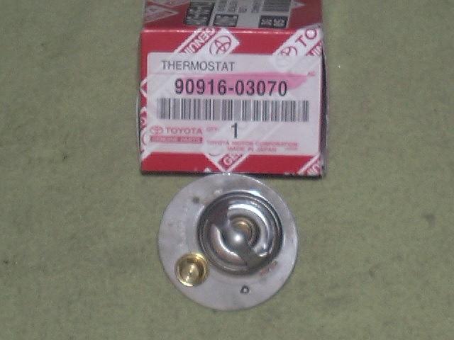
Thermostat:
After everybody looked at me like I was crazy for saying that it ran hotter with the heat on, I went to the dealership and bought t-stat part # 90916-03070. This did the trick. What happens on the 22R and 22RE engine, when the coolant goes through the heater core it gets cooled off enough that when it gets dumped back in on top of the t-stat it shuts it. Therefore the temperature in the engine continues to go up. The t-stat that I have mentioned has two valves in it, one at the regular temp. and one smaller on at a cooler temp. If the cool water shuts the big one, the smaller one stays open. The overshooting/spiking temperature gauge may also appear independent of heater operation.
All this may happen because of some flow instability in the cooling system or the lack of a by-pass hose, which on other systems, keeps hot coolant running on the t-stat. On the subject of the overheating thread, an engine can run hotter with no t-stat. But it would probably be a system configured differently than the 22re. Mine runs cold when the t-stat is removed. Just a minor change in components can trigger this problem. In my case, I had a rebuilt engine installed. No problems with the original engine, but the new one (block and head - same water pump, t-stat, radiator, etc.) was enough to trigger the temperature gauge overshoot.
So it was just something different in the coolant flow of the old block/head compared to the new block/head that triggered the problem in my situation. And since installing the 2-stage t-stat, I have had no signs of that problem since and this has been 13+ years now with the same t-stat in there. Other folks may find differing results, most have good results with the upgraded t-stat, but in some cases there is still some temperature overshoot going on. Why is this? Well, my feeling is that this problem is fundamentally due to a flow instability in the 22R/RE engine. Since it is usually related to use of the heater and that changes the coolant flow when the heater valve is open, this would explain that effect. As noted above, if the coolant is slightly cooled as it passes through the heater core, that cooler coolant dumping back onto the t-stat might be enough to "trick" it into staying closed. Before I changed to the new t-stat, I found that if I observed the gauge reading high, if I closed the heater valve for a minute or so until the t-stat opened up all the way, then I could slide the heater control back to hot and all was fine. So it just seemed to be related to the engine starting out cold and having the heater valve open, bypassing coolant through the heater core, that cased the temperature gauge to spike.
Another advantage of the 2-stage thermostat is that the thermal "inertia" of a thermostat is greatly affected by the mass of the temperature sensing element (a.k.a. slug) on the thermostat. The normal single-stage t-stat has one big valve with a large spring and a large slug to force the spring open. The 2-stage t-stat, on the other hand, has a tiny valve and a medium sized valve, with tiny and medium sized springs and slugs. This lets the smaller t-stat valve react very fast to engine temperature changes and the medium sized valve, although a bit slower, still operates faster that the one large valve.
A lower-cost version of this can be done by drilling one or more small holes around the edge of the single state t-stat to allow some coolant to flow all the time. This functions like the normal bypass hose on other engine designs.
On the subject of thermostats (or turd-mo-stats for Toy4x4 old-timers:-), I once tried one of those "fail safe" thermostats. A normal t-stat has a spring that holds the valve closed and the slug forces the valve open in response to coolant temperature. The slug has a sealed chamber with a temperature sensitive medium in it that expands when heated. The typical t-stat failure mode is that the chamber leaks or swells, preventing the t-stat from opening. The fail safe thermostat has a catch that is engaged when the t-stat valve opens fully and then the valve is held open. I guess the idea is that if the engine ever does begin to overheat, the t-stat locks open and prevents further damage. Well anyway, I had installed one once, and it worked fine. One day, I lost the silicone oil out of my fan clutch (didn't notice this until later when I popped the hood and saw the results) on a hot (100F) day. I recall seeing a slight temp rise once, but nothing too bad. Some weeks later, on a cool night, I turned on the heater and got almost no heat. This is when I popped the hood, saw the oil sprayed all over and put two and two together. Pulled the t-stat out and sure enough, it was latched open, so I guess it did its job. However, I now had to replace the t-stat, since once it locks open, it can't be reused. But I guess this also shows the engine runs cooler with at least a wide open t-stat in it.
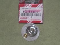
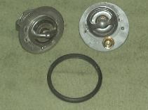
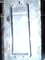
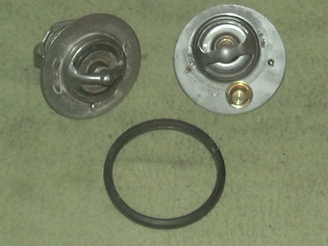
90916-03070 09916-03078 vs. 90916-03070 - NOTES:
- Buy 2-stage thermostat, Toyota P/N: 90916-03070
- The above pictured 2-stage unit was purchased 3/25/03 from my local Toyota dealer. I'm still running that same unit in 2026!
- The stock is thermostat listed for my '85 22RE is #90916-03078 and is pictured in the right image (upper left corner)
- Both are stamped 88°C (190°F)
- Both the 070 and 078 thermostats are the same diameter, use the same o-ring gasket and have the little "jiggle" breather valve
Rating:
/2
Why 2 numbers? The first is what I found in an old e-mail I had saved and was the p/n I ordered at my local Toyota dealer in 1998. Later, someone send me the 2nd number given to them by a Toyota parts counter. My guess is the older p/n was superseded by the new p/n, apparently both fit the thermostat housing, both open at 88°C, if it looks like a duck and sounds like a duck, its a duck!
And, in case you think I'm making this all up, there is an honest to goodness Technical Service Bulletin (TSB) issued by Toyota for this very problem:
TSB: 029032787 22R-E Engine Temperature Overshoot
It says:
Some 1984 pickup trucks and 1983-1984 Celica models, equipped with 22R-E engines, may experience a condition called "temperature gauge overshoot". After starting a cold engine the temperature gauge will indicate a higher than normal engine temperature for a short time just prior to the thermostat opening. After the thermostat opens, the temperature gauge will return to the normal range. A new double valve thermostat has been made available to reduce temperature gauge overshoot.
And calls for part number 90916-03070 which according to the TSB replaces 90916-03055.
Now, why they say this only affects 83-84 engines is beyond me (there may be other TSBs) but my '85 has this exact problem and this part corrects the problem. I have been running the same thermostat now for at least 7 years, it is still working fine, I suspect that the smaller t-stat valve handles most of the temperature fine tuning and saves the larger valve for the large adjustments. This division of labor saves wear and tear on the moving parts and with two valves, you have a sort of built-in redundancy of function. I have heard you can also drill a small hole (1/16" or so) in the base of the thermostat flange and get a similar effect.
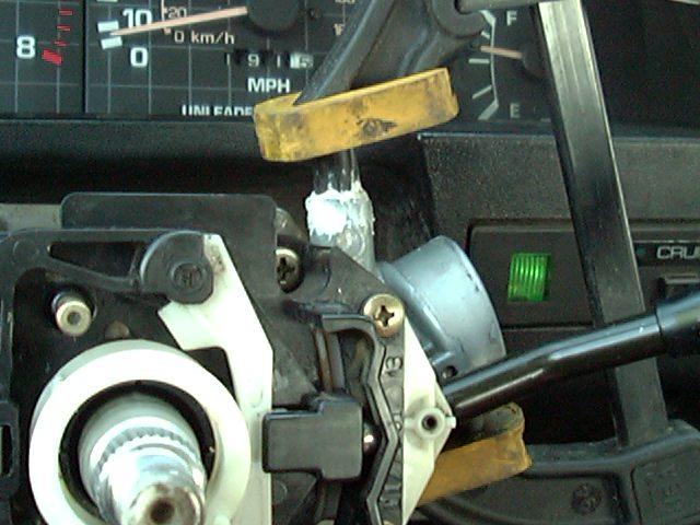
Where is the thermostat located and how do you change it?
It is under the thermostat housing (or neck) beside the valve cover. A sure fire method to locate the thermostat on most engines is to follow the upper radiator hose from the radiator back to where it connects to the engine. Usually the t-stat is located right there:
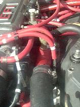
22R/E T-stat Location In the above image, the t-stat housing is between the EFI intake plenum and the valve cover. It is painted red in the above image, buried beneath a few vacuum lines. With a cool engine. mark and remove the lines to access the cover and drain a quart or two of coolant from the radiator drain valve. Disconnect the temperature sender(s) wires, the upper radiator hose and remove the two retaining bolts (12mm head). Lift off the housing, take note of the old t-stat orientation (i.e. which side is up) and then remove the old t-stat and gasket.
Check that the gasket surface is clean and smooth, install the gasket around the t-stat, drop it in place with the "slug(s)" down. Replace the housing and apply some anti-seize compound to the bolt threads and insert them. Tighten them down snugly, replace the vacuum lines and electrical connectors and refill the cooling system. Run the engine to temperature with the radiator cap off to allow any trapped air to vent, then put the cap on and check for leaks.
Also a good idea to test a new t-stat prior to installation. Drop it in a pot of water on the stove and use a thermometer to see at what temperature it opens and that it opens fully. I will usually test the old t-stat as well, to see if it was defective or not.
Note:
You may find 1 or more temperature senders screwed into the neck of the thermostat housing. What do these various senders do you might ask? Well, it all depends on what sort of setup your truck has.
- If you have A/C, there is a thermo-switch in the housing that feeds the A/C Amplifier (behind the glove box). That switch is used to shut of the A/C compressor if the engine coolant temperature rises too high (to prevent overheating).
- If you have an automatic transmission, you may have a sender there that feeds the ECT computer. It is used to sense engine temperature and lock out use of overdrive until the engine has reached it's normal operating temperature.
- If you have a turbo-charged engine (22-RET), there may be a sender there that feeds into the main EFI ECU that is used to affect the turbo operation in case of engine overheating.
Steering Stabilizer Removal:
Want to replace that inadequate, leaking stock steering damper? Well, you'll need to get the rod end out of the tie rod first. If Liquid Wrench and the BFH don't work (never seen it work yet) take out the trusty Hot Wrench (i.e. torch, propane that is) and heat the stud until the grease/boot on the other side just starts to smoke. Put down the Hot Wrench and grab the BFH and one or two taps and it'll fall right out. You don't want to heat the tie rod itself, just the end of the stud.
Same trick works on tie rod ends and other stubborn tapered studs. The heat causes the stud to expand and it also helps loosen whatever is holding it in, then the brief delay in setting down the torch and picking up the hammer lets the metal cool/shrink a bit and the rest is history.
Hot tip:
The factory steering damper has a set of rubber bushings on one end and what appears to be an honest-to-goodness tie rod end on the other end. Before chucking it in the dumpster, take a hack saw and slit the loop end and pop that rod end out. You'll have a spare rod end and boot for your parts box! Not exactly sure if it is replaceable, but the nut, boot and retaining spring are worth saving.
Cost:
Next to nothing
Rating:
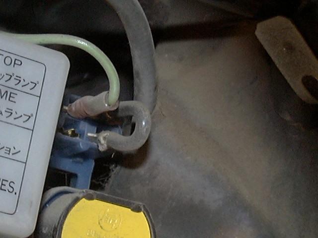
Power Windows:
I love the power windows in my 4Runner, makes it easy to roll them up in the dust or down to hear the spotter's instructions. One thing that I don't like is that you need the ignition on to operate the windows. If it was just the ACC, I wouldn't mind so much, but the ignition, come on!
A quick look at the wiring schematic for my model, shows there is a relay that is powered by an ignition lead that connects the power window switches through a circuit breaker to the battery. I guess this must be some sort of security or safety feature, but it seems that if you just jumper across the relay contacts, the windows will operate any time you want. Since the power is already fed through a 20A breaker, there is no electrical safety problems involved. I fashioned a short piece of 12-ga wire with a spade lug on each end end that fit into the two contacts where the relay plugs into. Just be sure to jumper across the relay contacts and not the relay coil.
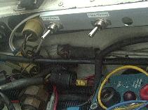
The relay and circuit breaker are behind the kick panel on the driver's side, above the cruise control module (see photo below). My circuit breaker was bright yellow and the relay was above it. The heavy black wire shows where I jumpered my relay contacts. I used crimp-on, uninsulated spade lugs to insert into the relay socket.
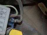
- NOTES:
-
The green wire is my source of switched 12V power, which I run to a
terminal block and then attach various loads needing switched power. It
is not needed for this modification, I only mentioned it here because
its in the picture.
- On later model trucks, there is a full relay control box for the power windows, unlike the switch-only setup on the '85 and earlier models. If so, the relay module will be located in one of two places. It'll either be inside the driver's side window, near the switches, or under the dash near the e-brake handle. If one of these two setups are present, any wiring mods will need to be done by re-powering the relays there and this simple one-wire jumper will not work.
- There are typically two other relays in that area. Towards the back is the turn signal flasher relay and in the middle, the tail light relay.
- On later model trucks, there is a full relay control box for the power windows, unlike the switch-only setup on the '85 and earlier models. If so, the relay module will be located in one of two places. It'll either be inside the driver's side window, near the switches, or under the dash near the e-brake handle. If one of these two setups are present, any wiring mods will need to be done by re-powering the relays there and this simple one-wire jumper will not work.
Check out my YouTube videos on power windows:
- How to bypass the Power Window/Main Relay
- About the power window system
- Power Window changes over the years
Rating:
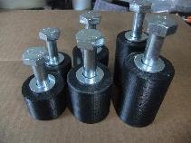
Seat Height Adjustment:
I've got the driver's side Sport Seat (must have a bazillion SR-5s in the fabric) in my 4Runner. I really like it's adjustability and comfort. My only real complaint is that its not well suited for off-roading. I'm not short (just under 6') but I felt like I was sitting down in a hole in the seat. The back of the seat was too low and the forward adjustment of the back rest is too far back for my liking if I wanted to look over the hood to see where I was going.
Looking at the seat frame, I saw that the frame just bolts to the floor in back. I pulled a bolt (M10x25mm 1.25 pitch) and figured I could get a longer bolt and stuff some thick washers under the frame. I used 8 - 1/8" thick washers to give me about 1" of lift. I basically measured my head clearance (to the roof) and split the difference. While 1" doesn't sound like much, it makes a world of difference in visibility. Also, the highest setting on the seat back adjustment is now more upright which gives a much better off-road driving position.
I added a 1" seat lift on the passenger side as well. The actuator cable under the passenger seat broke (a common occurrence on the 2-door 1st generation 4Runners), so in order to replace it, I needed to pull the seat out. With the seat stuck back, it was nearly impossible to get to the two rear bolts. So after replacing the cable, I installed spacers under the seat supports. The added space under the passenger seat should make fixing the cable next time it breaks a whole lot easier.
Raising the rear of the seat will help to alleviate lower back pain and leg numbness on long drives. As you raise the rear of the seat cushion, you rotate your pelvis into a less acute angle. It also takes the pressure of the front of the seat cushion off the back side of your thighs, which improves circulation and comfort. The angle change is approx. 4 degrees per inch of lift. Imagine sitting on the floor with your knees up under you chin compared to sitting in a regular chair with your pelvis at closer to a 90 degree angle, which is more comfortable?
A seat lift kit will cost much less than expensive orthopedic cushions for the seat. Note that the front of the seat frame is typically mounted into a raised section of the floor with horizontal bolts. So it is not possible to raise the front of the seat as spacers there would slide the seat forward and that would make the rear mounting holes not line up.
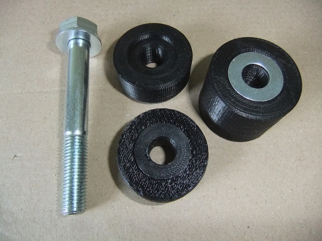
Parts:
  16 Fender Washers
  2  10mm bolts
  -----------------
Rating:
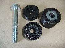
Update:
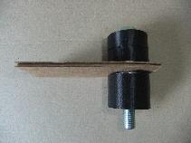
While the above solution of stacked washers worked, it was a real hassle to get two stacks of washers to all line up to drop the bolts through with one hand while holding up the seat with the other hand. So 4Crawler Offroad designed some spacers, shown above. Note that the installed image is of the 1" dia. white spacer used in the prototype (still in use on our shop truck after 15+ years). The current production spacers are made of a black ABS plastic which is a a tough plastic commonly used in protective sports gear like football helmets. The ABS plastic can easily be painted if you want to color match it to your vehicle interior. And due to customer demand, we're now offering adjustable height seat lift kits in ABS, capable of 1", 1.5, 2" or 2.5" lift in one kit, details below.
If interested, 4Crawler Offroad can now supply you with 1", 1.5", 2" or 2.5" tall seat lift spacers and longer-than-stock grade 10mm metric bolts for an easy bolt-in seat lift, as shown below. Each kit includes 2 spacers (or stack of spacers) and 2 longer than stock bolts and washers to lift the rear of one bucket seat:
- Order seat lift kits here...
- Will this kit work on my vehicle?
- Installation
-
Note:
- 1" = 25mm, 1.5" = 38mm, 2" = 50mm, 2.5" = 63mm
-
These kits will raise the REAR of the seat only:
- The front of the seat remains at the same height as before
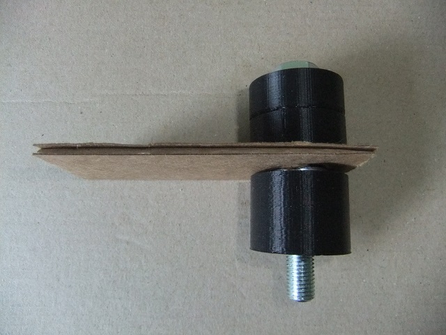
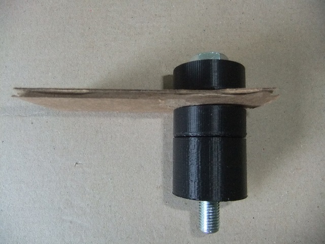
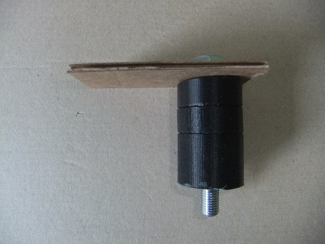
Seat Lift Kits, 1", 1.5", 2" Seat Lift Installed And our new adjustable height kits, 1"-2" and 1" - 2.5" (1"-2.5" has a longer bolt and 1 extra 1/2" spacer). The adjustable height kits are ideal if you are unsure of the height seat lift works best for you. Using the power of 3D printing, the spacers can be stacked securely up to the desired height and then any left over spacers are used on top of the seat bracket to take up the extra bolt length. You start with the 1" spacer on the bottom, add 0 or more 1/2" spacers on top of that, then fill the top spacer recess with one washer. Then the seat bracket sits atop the spacer stack and any remaining spacers sit on top and a second washer is used under the bolt head to secure everything together.
1" - 2" Adjustable Height 1" Lift 
1.5" Lift 2" Lift Installation:
If concerned about air bag sensors, you may wish to disconnect the vehicle battery during installation. In most Toyota vehicles, there are typically 3 air bag sensors, 1 in each front corner between the radiator core support and the front fender. The 3rd sensor is located in the center console area, below the radio.
First step is to remove the original seat bracket bolts with a wrench or socket. For Toyota, this will be 14mm or 9/16". Be aware that the bolts may protrude below the vehicle floor. As such, they can pick up dirt and rust from that exposure. Be sure to check that the threaded hole is free of debris and that the new bolts can spin down without binding. If dirty, try blowing the hole out and keep running one of the original bolts in and out of the hole until it's nice and clean. You don't want to have the new bolts gall up inside the threads because those are typically nuts welded to the floor of the vehicle. If you apply too much force, you can break that nut free.
Then lift the rear of the seat up and slide a seat lift spacer under each end. Insert the longer bolt and washer supplied in the lift. You'll need a 17mm wrench or socket to tighten the new bolts. Tighten them up snug, around 5-10 ft.lb. (7-11 Nm) torque should suffice. Unlike the stock setup where you have the steel seat bracket bolted directly to the steel floor pan, the seat lift spacers offer a small amount of compliance to help keep the bolts from loosening up under road vibration. The bolts just need to be tight enough that they will not vibrate loose. Do not torque the bolts to the factory specified value as that assumes you have the seat bracket directly on the steel floor panel. Be sure to check them after 100 mi. or km. of driving to make sure they've not worked loose. And check your side and rear view mirror adjustments as you might need to correct those prior to driving.
With the adjustable height spacers, you'll generally need to run all the spacers or you may find the threads on the bolt bottom out in the nut below the floor pane;. If you find you want to run with a shorter lift height and want to eliminate the stacked spacers on top of the seat bracket, you can pick up shorter bolts at a good hardware store or contact us and we can supply shorter bolts.
One thing you may run into when installing the longer bolts is getting them to thread into the existing holes and captive nuts in the floor of the vehicle. The factory bolts are usually of a self-aligning design to aide in automated assembly at the factory. After all, you can't be waiting around for some worker to hand start all those seat bracket bolts before driving them in with an impact wrench. Instead, tapered, self-aligning bolts are dropped into the holes and then are driven home. But if that bolt takes a while to line up with the existing threads, it can partially deform the upper threads making it hard to get a straight threaded bolt started. Also, since you typically can't see the captive nut under the floor, its hard to see if the bolt is going in straight or starting to cross thread.
- Usually you can run the factory bolt in and out of the hole a few times, possibly with some lubricant, to clean up the threads.
-
Some other options if you can't get a bolt to start are:
- Take a file and lightly taper end of the bolt. Lightly file in the direction of the thread, rotating the bolt every few strokes. You're looking to just remove the sharp peak of the bottom few threads to help the end of the bolt fit into the nut under the floor. This won't affect the strength of the bolt as that end will be sticking out below the nut.
- Or, if all else fails, pick up a matching thread tap and use that to chase out the threads. The Toyota kits use M10-1.25, the Jeep kits M10-1.50, you can find single taps at a hardware or auto parts store, or on-line, for example Amazon.
Seat lift kits are available:
-
A seat lift kit consists of:
-
One pair of ABS plastic spacers to raise the rear of the seat bracket
up off the floor.
- They are only loaded in compression,
-
One pair of bolts and washers of suitable length, in the same
grade/strength as OEM for safety
- Note, raising the rear of the seat 1" will only tip the seat bottom about 2°, so generally does not cause you to slip forward in the seat, it is tilted backwards by a greater angle than that.
-
One pair of ABS plastic spacers to raise the rear of the seat bracket
up off the floor.
-
Will fit either driver or passenger bucket seat
- Order 2 kits if you want to raise both seats
- Can use 2 different height kits if driver/passenger are of different heights
-
Bench seats:
-
Some bench seats have 2 rear brackets, (1 on each side) and some have 4
brackets (1 each side and 1 each side of the tunnel)
- Order 2 kits if you want to raise a bench seat if that uses 4 rear mounting bolts, these may need 2 different size bolts, see below...
-
Some bench seats have 2 rear brackets, (1 on each side) and some have 4
brackets (1 each side and 1 each side of the tunnel)
-
Be sure to check your head-roof clearance as you currently fit in the
vehicle.
-
Typically 1" lift kit will work for folks up to 6 ft. tall,
2" kits generally for folks under 5 ft. 6 in. tall.
- Also available are our adjustable height kits which allow 2 or 3 different heights to be selected with a single kit if you're having a hard time deciding on one single height.
- After all, the whole idea of the seat lift kit is to find what height works best for you. There's no formula to tell you what that height is.
-
Typically 1" lift kit will work for folks up to 6 ft. tall,
2" kits generally for folks under 5 ft. 6 in. tall.
-
The kit will raise the REAR of the seat only, the
front of the seat remains at the same height as before
- Why the rear of the seat only? Well think about how you sit, it is your b*tt that determines how high you sit, if you lift your b*tt up, you raise your head up higher. If you lift your thighs, your head will stay in the same place.
- Also, the front seat bracket bolts are typically run horizontally into a raised portion of the floor, so putting a spacer under that bolt would only move your seat forward, not up. And since those front bolts are more horizontal, the front of the seat bracket simply pivots around those front bolts when you raise the rear. Since the front seat mount bolts are in a horizontal orientation they resist the front-back forces while the vertical rear bolts resist the up-down forces. And also note that the seat belts are not attached to the seat at all.
- If you are unsure of what height kit you might need, try test fitting some blocks of wood under your rear seat bracket and do a test "sit" in your driveway. That way, you can see how one height or another feels to you.
- Contact us if you have any questions about our seat lift kits not answered below.
-
Known to fit the following make/model vehicles:
-
TOYOTA:
- '84-'95 Toyota 4Runner / Hilux Surf
- '84-'95 Toyota pickup / Hilux and T-100 pickup models
- '82-'85 Toyota Celica
-
FJ
Cruiser and 4th/5th gen 4Runner seats.
- Will fit 3rd gen 4Runners if the rear seat mount bolts are vertical into the floor.
-
2005-2021 Tacoma pickups have the vertical rear seat bolts so the seat
lift kits fit these models.
-
Review: //www.tacomaworld.com/forum/product-reviews/334521-raise-low-slumping-seat.html
- Note, some later model (~2014+) Tacoma pickups do not use bolts to attach the rear of the front seat to the floor, so be sure to check your truck prior to ordering.
- The 1995.5-2004 Tacoma pickups used a non-vertical rear seat bolt so the seat lift kits will not fit those models
-
Review: //www.tacomaworld.com/forum/product-reviews/334521-raise-low-slumping-seat.html
- Also seems to work with the earlier model Lancruisers, basically any model with vertical (10mm thread diameter, 14mm head size) rear seat mounting bolts.
- Note that this kit requires that the rear seat bolts insert vertically into the floor, not at an angle like on the '95.5 - '04 Tacoma pickups and 3rd gen. 4Runners, so of course it is not applicable to those vehicles.
- For vehicles with non-vertial seat bracket bolts, Seat Jackers might be an option.
-
HONDA/ACURA:
- Crosstour and other Accord-based models
-
CRV:
- Just check the orientation of the rear pair of bolts holding the front seat bracket to the floor, as noted below.
- MDX
-
JEEP:
- 2007+ Jeep JK Wranglers and other vehicles with M10x1.50 seat mount bolts also available below.
-
For other vehicles, will this
kit fit? Here is how to find out:
-
Look at the back of the seat bracket where it is attached to the floor.
Do the bolt(s) there go straight down into the floor? If yes, the kit
may work, if not, it won't work.
- If the bolts are vertically oriented, what size are the bolts (length under the head and diameter/thread pitch)?
-
If the bolt length is around 1"/25mm and the thread size is
M10x1.25 (a bit over 3/8"), then yes, the kit will fit.
- The Jeep JK kits, below, use an M10-1.50 bolt that's about 40mm long at stock height, so order one of those kits if you need that size hardware.
- If the bolts are a different size, let us know the bolt specifications and we can see if a custom kit can be designed for your application.
- For Toyota Hilux pickups, that came with a factory bench seat, you may have 2 different size bolts on each side, that being M10-1.25 and 7/16-20. If so we now have a hardware option for that, each pair of seat lift spacers will come with a bolt of each size.
-
If "vertical orientation" throws you off, look at it this
way:
- If you unscrewed the bolt, could you slide a spacer between the seat bracket and floor and have the bolt still line up with the hole in the floor?
- And if you were to hold that bolt above the hole in the floor and then dropped the bolt, would it fall down that hole?
- If the answer to the above two questions are yes, then your seat bracket is suitable for a seat lift.
-
If you use this kit on a vehicle not listed above, let us know so we
can update the fitment information.
- We try to list every vehicle we have heard these kits will fit based upon customer feedback. If you want to know if the kit will fit your vehicle, simply check how the rear of the front seat is attached to the floor, as noted above.
-
Look at the back of the seat bracket where it is attached to the floor.
Do the bolt(s) there go straight down into the floor? If yes, the kit
may work, if not, it won't work.
-
TOYOTA:
Use the convenient on-line ordering buttons below to place an order:
- One kit will lift one bucket seat. If you have 2 bucket seats or one bench seat you want to lift, order two kits.
- Kits include a pair of spacers (adjustable height kits have additional stacked spacers) and a pair of longer than stock seat bracket bolts metric class 8.8 to replace the OEM bolts of the same class.
- We have a limited stock of our seat lift kits.
-
Fixed height kits:
- 1" / 25mm (p/n: 1inSeatLift) - US$16.00/kit plus postage
- 1.5"/ 38mm (p/n: 1.5inSeatLift) - US$19.00/kit plus postage
- 2" / 50mm (p/n: 2inSeatLift) - US$22.00/kit plus postage
-
Adjustable height kits:
- 1"- 1.5" (p/n: 1.5adjSeatLift - US$25.00/kit plus postage)
- 1"- 2" (p/n: 2adjSeatLift - US$29.00/kit plus postage)
- 1"-2.5" (p/n: Toy2.5adjSeatLift - US$35.00 plus postage)
-
Hardware options:
- M10-1.25 bolts for Toyota/Honda/Acura
- M10-1.25 - 7/16-20 bolts for Toyota bench seats
- M10-1.50 bolts for Jeep
- 7/16-20 bolts as needed
-
Shipping:
- Ships in USPS First Class or Priority Flat Rate envelope
- Shipping weight 5-10 oz./kit
- Multiple Item Order link if you want to order a seat lift with other items or multiple heights
- Returns and exchanges
- Cancellation Policy
< 1" seat lift kit / 1" seat lift kit 1"/25mm seat lift kit ~~~~ ~~~~ ~~~~ 1.5" seat lift kit 1.5" seat lift kit 1.5"/38mm seat lift kit ~~~~ ~~~~ ~~~~ 2" seat lift kit 2" seat lift kit 2" seat lift kit Adjustable Height Seat Lift Kits:
By popular request, we now have adjustable height seat lift kits. The adjustable height kits are perfect if you are unsure of the height seat lift that will work best for you. These kits feature a 1" (25mm) tall base spacer and then 1, 2 or 3 additional 1/2" (12.5mm) tall stackable spacers that interlock to form a stable column. For the full height, stack all the spacers up. For less heights, remove spacers from below the seat bracket and then, if needed, stack them on top of the bracket, to "shorten" the bolt if you find the bolt is bottoming out in below the floor. If you find you want to run with a shorter lift height and want to eliminate the stacked spacers on top of the seat bracket, you can pick up shorter bolts at a local hardware store or contact us and we can supply shorter bolts.
1.5" adj. seat lift kit 1.5" adj. seat lift kit 1.5" adj. seat lift kit ~~~~~ ~~~~~ ~~~~~ 2" adj. seat lift kit 2" adj. seat lift kit 2" adj. seat lift kit ~~~~~ ~~~~~ ~~~~~ 2.5" adj. seat lift kit 2.5" adj. seat lift kit 2.5" adj. seat lift kit
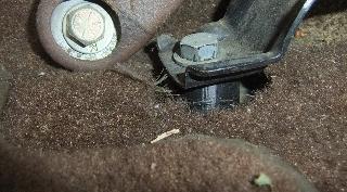
1st gen. 4Runner Center Console Update:
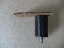
One issue I've encountered, and recently did something about, was that the seat lift left the center console too low to comfortably rest my right elbow on. I lived with this for about two years, then after breaking my motor mounts on a wheeling trip, I discovered that the broken mounts had allowed the rear transfer case flange to tilt up and into the rear heater hoses. If you have a dual transfer case in a 4Runner, you know what I mean. I even had a 1" body lift at the time, but there was only 1/4" at most clearance between the spinning flange and the rubber hoses.
So, how to kill two birds with one stone? Simple, raise the rear heater (and thus the center console) about 2". This will place the rubber hoses right up under the floor board, and lift the console to a more comfortable height. M6x60-1.25 bolts and a wooden spacer block work great. To the brass heater core tubes, I soldered on a 1/2" NPT threaded adapter, screwed in a 1/2" brass street elbow and a 1/2" hose barb fitting to drop down through the floor and turn the sharp corner so the rubber tubing will connect in a straight line.
[back to the top]Replacing Light Bulbs:
While trying to find the resistor pack to fix my inoperative blower motor, I looked all over under and behind the dash. That time, as it turned out, was not wasted. I found that if you pull the two screws attaching the glove box hinges to the dash out, the whole glove box can be taken out, revealing all the guts inside the dash. A real handy way to get to a lot of the stuff back there. And if you look up (w/ head on the floor) where the glove box was, you'll see the little light bulb that is *supposed* to illuminate the box when it is open. Mine didn't, but now it does. It's a mini-bulb, same one (Sylvania #74 bulb) that is used behind the heater controls. Is it a coincidence that there are two of these bulbs and they come two to a package?
Speaking of the heater control lamp, mine was also burned out. To get to that gem, you simply have to slide the heater controls to the middle, pull the knobs off and then pry out the plastic face with a small screw driver. The mini lamp socket is behind the face. I found it is not very well supported from the back and when I pushed in the bulb, the socket popped out. It works best if you slide one finger up from behind to hold it in place while pushing in the tiny lamp.
Cost:
Varies, minimal
Rating:
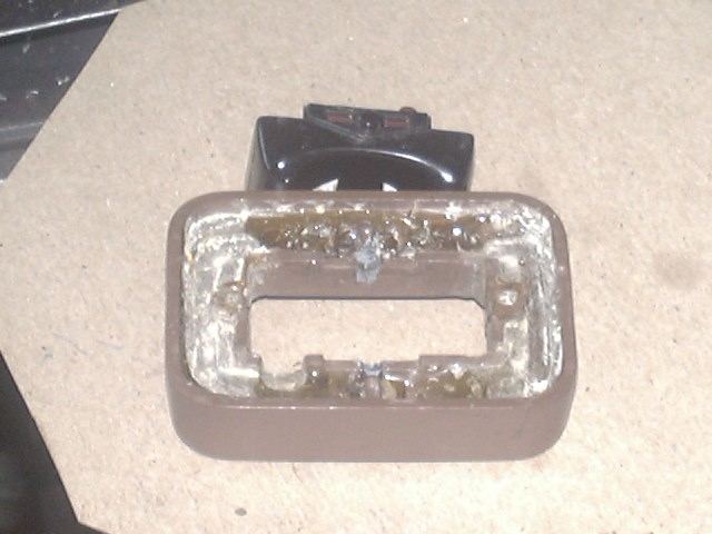
Window Switch Repair:
When I bought my 4Runner, the previous owner commented he was having trouble with the passenger side power window. Had taken it to a shop several times, all sorts of checks were done but the problem persisted. It worked fine from the driver's side switch but the passenger side was intermittent.
I pulled off the switch by unscrewing it from the back of the door panel. It turns out that the switch sandwiches the door panel, the front piece has the rocker and the back piece has the electrical contacts. In my case, both of the screw holes were badly stripped and the problem was when the rocker was pushed, the spring force would separate the switch halves, preventing the contacts from mating.
I took off the front piece and filled it up with epoxy and let it cure. Then I used a Dremel tool and drill press holder (forming a simple but effective milling machine) to mill out the epoxy enough to allow the back piece to mate to the front. Then I re-drilled the screw holes and re-attached the switch to the door. Works like a champ now!
Well, it worked for a few years anyway. When the switch started acting up again, I decided to tear it apart again, thinking the screws had stripped out again. Turns out they were fine, the earlier epoxy repair was still holding up fine. So, its was time to investigate the underlying cause of the problem. Looking at the passenger side switch, I figured out how it works. Basically, it does all the interlocking to prevent simultaneous operation by the driver and passenger side switches, which might cause a short circuit. All the switch does is provide power and ground to the power window motor, one polarity to raise it, the opposite to lower it. The passenger side switch has 2 pairs of contacts, one normally closed and one normally open. The normally closed contacts pass the signals from the driver's side switch to the passenger side motor, the normally open ones drive the passenger side motor directly. This all functions via the rocker in the passenger side switch and its position inside the switch assembly itself.
So what does this all mean? I found that while the driver's side switch would work the passenger side window just fine, it did not work from the passenger side switch. Turns out the rocker had worn the pivot point in the switch face a little deeper over time, this let the rocker move away from the contacts just enough that it could no longer close them when depressed. Simple fix was to build up the pivot point with some JB Weld, which is shown below:
Window Switch Repair After reassembling the switch, I found it worked perfectly from the passenger side (Woo Hoo!) but no longer worked from the driver's side (Bummer!). Then it dawned on me that it was the rocker being perfectly centered in the housing that was key, as if it were too far from one side, those contacts were not made up and no power would flow. So I carefully whittled away the built up JB Weld until the rocker was perfectly centered and both driver and passenger side operation worked. Took a half dozen tries to get it dialed in, but now its finally working as designed. And, an added benefit is that the passenger side window now goes up and down faster, since the switch is making better contact, there is less resistive loss in it and more power is getting to the motor.
Cost:
Minimal
Rating:
Center Console Upholstery:
Mine was worn out, leaving a tattered cloth backing that allowed the foam to yellow and shred in the sun. Also the front latch was broken off and the hinges were very loose and the whole thing rattled with every bump.
Unscrew the hinge, take off the base plate and the cushion will lift off. Carefully remove the old vinyl, you'll need it for a pattern on the new vinyl. Go to fabric store with the old vinyl and try to find a close match. You'll need six inches or so, but they want to see you a yard. After ripping out the seams on the corners, flatten out the old vinyl on the new and trace a pattern for the new piece. I found it best to iron out the old cloth backing and tape up any tears get the best fit. Also, it works to fold the old vinyl in half lengthwise and take the average between the edges. Be sure to include some index notches when cutting out the vinyl to make it easier to sew.
Sew up the corners, turn the cover right side out and you are ready to install it. I added a piece of 1/4" closed-cell foam over the existing foam after trimming off a like amount to fill in where chunks were missing. Screw everything back together, get a new latch (if required) and you now have a very handy place to rest your arm while driving.
Rating:
[Last updated: 18.February.2026 ]
Visitor # since 28.AUG.2001


 ===>>
===>>