Driveline/Propshaft 101
Contents:
Back to my Cheap Tricks main page.
![]()
Introduction:
This page is a collection of information I've collected over several decades concerning driveshafts and their setup and alignment. I'm not an expert in this subject, but I've tried to only use information that seems to make sense from first principles. If you find anything incorrect or anything that should be added, please send that in an e-mail with references.
Have you noticed a vibration or rumbling noise when you are driving down the highway? If you have a lot of miles on your truck, have modified the suspension or drive train in any way, you may be experiencing driveline vibration.
From what I've researched, ideally you want the two ends of a double u-joint drive shaft within 1°-2° of each other for maximum u-joint life and minimum vibration. This is actually the operating angle (under load) and not the angle of the drive shaft to the u-joints themselves (that has its own limit).
Since the rear pinion moves up under acceleration (unless you have anti-wrap control on the axle) ideally you set up the static pinion angle to be 1-2° below the transfer case output flange angle. This way, as the pinion twists up, it comes into a good alignment with the transfer case. Typically, this figure won't be listed in any service manual, but I did find a reference from Ford that lists a static angle of difference of 1.7°.
In my case, I had installed a 1.5" longer shackle and a 3° shim to compensate for the extra tilt of the shackle. I never measured the angles at the time. Later, I did measure and found even with 3°, I was still 1° above the transfer case and I needed to add another 2-3° to get me passed zero and into the desired range. So I have to conclude that originally my pinion angle was off with the stock shackle as well. Driving experience also confirmed this, I had drive line vibration under load (pinion tips up), but it would go away under coasting conditions (pinion tips down).
So my point is to measure what you have now and see if its OK and how much will it change with a longer shackle.
I recently installed a CV-style rear drive shaft and had to tip the pinion up to point directly at the transfer case, so there a longer shackle works to an advantage. I calculated I would need an 8° shim with my 7" (3.5" longer than stock) shackle, but after installing everything, found my pinion was about 2° high, so I made a custom 5° shim to place it 1° below the transfer case line. If you need a custom axle shim, I may be able to help you out.
Terminology:
Single Cardan joint or U-Joint:
The universal (or u-) joint is considered to be one of the oldest of all flexible couplings. It is commonly known for its use on automobiles and trucks. A universal joint in its simplest form consists of two shaft yokes at right angles to each other and a four point cross which connects the yokes. The cross rides inside the bearing cap assemblies, which are pressed into the yoke eyes. One of the problems inherent in the design of a u-joint is that the angular velocities of the components vary over a single rotation.
The universal joint was actually invented around 300 B.C. by the ancient Greeks. It was later re-invented in the 16th century by the Italian physicist Geronimo (or Gerolamo) Cardano who used it as a mounting gimbel for holding a ship's compass horizontal in rough seas. Fun fact, Cardano also published the famouns cubic equation formula (big brother to the famous quadratic formula). Finally, it was re-re-invented in the 17th century by the English mathematician Robert Hooke who used it in its common form for transmitting torque. If that name sounds familiar, that is because he also is famous for Hooke's Law, which states that the stress in a spring is proportional to the strain (i.e. the spring rate). Where would 4-wheeling be without springs and u-joints? And I guess Hooke fooled around with a microscope looking at plant cells or something. So for some reason, the term "Cardan Joint" has stuck and is used interchangeably for a universal joint.
Single Cardan is also a term for a driveshaft with one universal joint at each end of the assembly. So actually there are two single cardan joints in a single cardan drive shaft.
Here is an animation of a single-cardan drive shaft as it rotates.
Dana-Spicer put together this excellent YouTube video showing how a single-cardan shaft works.
And note, it's "Cardan", not "Cardigan" which is alternately a sweater or a Swedish singing group :)
Double Cardan Joints:
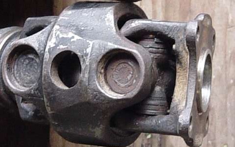
Double Cardan joints are a class of joint which are designed to mostly eliminate the variation in angular velocity that plagues u-joints, thus they're generally classed as a Constant Velocity. The simplest CV joint is simply two u-joints (or single cardans) connected end to end, usually the center section is called an H-yoke because of its shape. In this manner, the angular velocity variations of one joint are mostly canceled by the joint on the other end. Since there are two joints, the operating angle capacity of the double cardan joint is twice that of a single cardan joint.
These are the type of CV joints most commonly used on driveshafts connecting a transmission or transfer case to a rear or front axle. It's not a perfect "constant velocity joint" in that is is not truely constant velocity, but it's close enough for many applications.
More complicated CV joints utilize a multi-ball bearing assembly that rides inside a cup-shaped housing that allow the center section to rotate in a different orientation than the outside part like the Rzeppa CV joint. Further variations on CVs allow for "plunge" or in and out travel of the center section relative to the outer section. A combination of the two is often used in FWD applications, where a plunge-type CV is used on the transaxle and a ball bearing CV is used on the outside. The plunge capability allows the drive axle to lengthen and shorten as the suspension travels. The outer CV can handle greater angles to allow for both steering and suspension travel. These type of CV joints are most commonly used on FWD automobiles and on 4WDs with independent front suspensions. More information on CV joints may be found on the following web page: //wikipedia.org/wiki/Constant-velocity_joint
A CV joint often requires special lubrication, usually an EP moly grease that is very sticky. On exposed CVs, a flexible boot contains the grease, on internal CVs, like the enclosed Birfield-type joint on 4WD front axles, the grease is packed around the joint inside the steering knuckle.
Double Cardan is also term used when describing a one piece driveshaft with three (or more) universal joints. What a double cardan will do, is split a universal joint operating angle into two separate angles that are exactly one half of the original angle. Normally a Double-Cardan style driveshaft is used in applications where it is not possible or practical to properly align the ends of a driveshaft for a single-cardan setup. Examples include where the operating angle would be too great over a single cardan joint (see below) a double-cardan allows the operating angle to be split across the two halves of the joint. It is also possible to use two CV joints on a driveshaft which is commonly used where it is not possible to align either end of the driveshaft, such as when both vertical and horizontal misalignment occur, or when mismatched operating angles are present, such as in front wheel drive vehicles, where both up and down motion is present from the suspension travel as well as rotation about a vertical axis due to steering action.
Drawbacks of multiple CV joints are their higher cost and complexity as compared to u-joints, their extra length and weight, and their decreased maximum operating angle limitations. For example a single u-joint can physically operate at angles of 45° without binding up. A double cardan joint may bind up at angles of 30° or less without special clearancing to eliminate binding.
U-joint Operating Angle:
This is the angle formed between the two yokes connected by a cross and bearings. It may be a simple or compound angle, depending on the geometry of the driveshaft. While u-joints can operate at fairly high angles (usually up to 30°), the speed at which the shaft moves provides a practical limit to the angle as follows:
| SHAFT RPM | OPERATING ANGLE |
| 5000 | 3.25° |
| 4500 | 3.67° |
| 4000 | 4.25° |
| 3500 | 5.00° |
| 3000 | 5.83° |
| 2500 | 7.00° |
| 2000 | 8.67° |
| 1500 | 11.5° |
This table is based upon the joint at rated load and life. Going above the rated load or angle will decrease the u-joints life. As a general rule of thumb, for each doubling of the operating angle, RPM, or load, the lifetime of the joint is decreased by half. Rated lifetimes are on the order of 3000 hours.
In the typical off-road vehicle, a suspension lift is done to increase clearance and allow larger tires to be installed. To compensate for the larger diameter, lower gears are installed in the axles. Lets see what this does for the drive shaft, the lift increases the angle of the shaft and the lower gears means the shaft has to spin faster for a given axle speed, both things are working in the wrong direction on this chart. No wonder, driveshaft problems are common in vehicles modified for off-road use. And what speed does the driveshaft operate at? Actually, it runs faster than you think. Given a vehicle with a modest 0.85:1 overdrive gear in the transmission, the driveshaft is running nearly 18% faster than the engine is turning in top gear. So if the engine is turning 3000 RPM on the highway, the driveshaft is spinning over 3500 RPM.
Aside from u-joint lifetime, you also may be concerned with vibration-free operation at high speeds, at least for a street-driven vehicle. The maximum operating angle a given driveshaft can run depends on a variety of factors and is hard to give an exact number or formula to determine if a given setup will run smoothly or not. Some factors that come into play are the shaft RPM, the length and the tubing thickness. For example, a longer shaft can "soak up" more vibration than a shorter one and a slower moving shaft will vibrate less than a faster moving one. So, for an example. on my '85 4Runner I found that with the stock rear driveshaft running at about a 12° operating angle (approx. 4" lift, 50" long shaft), I had smooth operation. But when the shaft was shortened about 6" (due to adding a 2nd transfer case), the operating angle hit about 15° and I found it no longer operated smoothly, even with ideal u-joint alignment and a professional balance job on the shaft. So by converting the top u-joint to a CV joint and re-aligning the pinion angle, the shaft did run smooth again.
![]()
Measurements:
A frequently asked question is about driveshafts and angles and so forth, is "How much shim do I need for X" of lift" or "Is Y° shim too much?". Well, there really is no general answer to these general questions, rather the right answer is what works for that particular situation. For example, assuming that the driveshaft is aligned properly in a vehicle with stock suspension, if it is lifted with a block or spring lift, then everything should still be lined up, at least with a single-cardan driveshaft. It's like a parallelogram, the angles change, but the sides remain parallel. So why do some lift kit makers include shims with their kits? (Likely because they don't know what type of vehicle the lift will be installed on, so they supply parts that may or may not be needed in all applications). So the correct answer for how much to shim an axle to correct the driveshaft angles depends on how far off the angle is to begin with.
So, how do you go about measuring drivelines and angles, etc.? At first glance it seems kind of difficult, but I have some easy techniques that make the job very easy. How you measure the angles depends on the type of driveshaft you have. Also there are added complications when you have a 2-piece drive shaft, i.e. one with a ceter support bearing.
The number one rule of single cardan or u-joints is the sum of all the operating angles of all the u-joints in a shaft must equal to 0°. Now how close to 0° you need to get varies, some mfgs. say 0.5°, some say 1°. Toyota specifies 0.9° +/- 1°. When measuring the operating angle, that is the net angle across the joint.
For setting the drive shaft length, measure it from flange to flange at rest. You should allow at least 1.25" of compression on the rear shaft and maybe a bit more in front (1.5"-2" - assuming spring shackles in back) to allow for the suspension compression. Then, be sure you have enough spline travel at full droop. If the existing spline length is not long enough (sometime a problem in the front drive shaft) a long travel spline shaft may be needed.
A very important suggestion is to measure alll the shaft and joint angles BEFORE modifying your vehicle. This way you have a reference point to compare with after lifting or lowering the vehicle. As well, you'll be familiar with the measuring process and you'll be able to check that your pre-modification measurements "make sense". You should be able to see how the angles were set up at the facotry, assuming your drive shaft was running smooth when you made the measurements. You should also check the lengths of the shafts so you'll know if the drive shaft length has changed and may need something like a spacer to lengthen it.
Single-Cardan Measurements:
A single cardan or u-joint shaft is typically the least expensive and easiest to maintain type of shaft. U-joints are inexpensive and easy to maintain and/or replace. This shaft design tolerates changes in ride height well and spring or block suspension lifts typically have no affect on alignment. The main downside of this type of shaft is that the higher the operating angle gets, the more likely the shaft will vibrate. This will vary with the operating speed, shaft diameter, length, wall thickness and material. On my truck with approx. a 46" long shaft, when the shaft angle went above 12° it would no longer run smooth.
-
Assuming you have a single cardan
driveshaft and want to check if the transfer case output and pinion
flanges are close to parallel, just measure the distance between the
top and bottom of each flange.
- If the dimensions are equal, the two flanges are parallel.
- This style of alignment is called a Z Configuration or Arrangement since the shaft is similar to the diagonal in the letter Z and has equal, yet opposite angles top and bottom.
-
If they are not equal, then each 1/16" (1.5mm) difference is equal
to 0.9° across the ~4" diameter of the flange (which is the
size Toyota uses)
- Now is this were a single triangle, your correction angle would be this full 0.9° per 1/16" inch. However, in this case, since there is a u-joint involved, it has a "phantom center" and thus you are dealing with two triangles, one on either side of the center of the u-joint.
- Since there are two triangles, every change you make to one will also affect the other. Thus if you are say 1/4" (or 4/16") off top to bottom, if you shrink one side by 2/16", the other side will grow my 2/16" and the two ends will be parallel.
- So, one way to think about the correction is half of the difference in top and bottom lengths, 4/16" difference, 2/16" is half that, 2 x 0.9° = ~2°
- Or the other way is ~0.5° per 1/16" difference, 4/16" difference = ~2°
-
Other makes may use different size flanges and some may not use flanges
at all,
- If no flanges are uses, then an angle finder must be employed to measure the angles
-
Ideally, you would like the upper measurement to be 1/8" -
3/16" less than the lower measurement for a bit (1° -
1.5°) of static "down-angle". Then, as the axle (and
pinion) tilt up under load, the angles will approach parallel. While
this measurement can be done with the driveshaft in place, it may be
easier to do with it off, in order to get more accurate measurements:
In the above figure, you can see the red dimension arrow on top of the driveshaft and the green dimension arrow on the bottom of the shaft showing the distance between the driveshaft flanges. Note: some drive shafts do not use flanges, but the same concept applies. Pardon the crude ASCII art that is supposed to show a typical driveshaft: FT -|\ -| \ FB\ \ \ \ \ \ \ \RT \ |- \|- RB The idea is to measure (FrontTop -> RearTop) and (FrontBottom -> RearBottom) If (FT-RT) is equal to (FB-RB) then the angles are parallel Ideally, (FB-RB) should be a bit longer than (FT-RT) at rest -
Notes:
- f your driveshaft doesn't have flanges at the ends and instead has u-joint yokes, this technique may not work as well. In this case an inexpensive angle finder will do the trick. You may still need to be creative to find locations that allow you to measure the angles at the end of the shaft. See if the top or bottom of the differential or transfer case are parallel to the ends of the shaft or the u-joint yokes.
- And notice that nowhere in this discussion has the actual angle of the driveshaft been mentioned. Why? Because basically it does not matter. What matters is that the two u-joints at each end of the shaft have the same angle. That exact angle would of course depend upon the angle of the shaft itself, but it is only the relative angles (or difference in angles) at each u-joint matters. So if you have a 10° driveshaft angle and 10° on the top u-joint and say 11° on the bottom u-joint, you would have a difference of 1°. Now say the driveshaft angle were increased to 15°. Likewise say the upper u-joint angle also increases to 15° and the lower one to 16°. The difference is still 1°, so as you can see the driveshaft angle itself has no impact on the operating angle of the u-joint themselves.
So, why do the u-joint operating angles need to be the same on both ends of the driveshaft? To understand this requirement, you need to see how a u-joint operates as it rotates. For an easy case, assume no operating angle, that is 0°, between two shafts connected by a u-joint. As one shaft rotates through 360°, so does the other shaft, in exact unison, so at 0°, there is no issue.
- Note, that if you only have one u-joint on the shaft, such as in a double-cardan shaft, it therefore must be at a 0° operating angle.
However, lets angle the two shafts to say 45°. Now, look at the "cross" of the u-joint as it rotates. When the driving side of the cross is horizontal, it's ends are moving at the same speed as the yoke on the driving shaft. However, the driven side of the u-joint is 90° offset from the driving side, but since the u-joint cross is rigid, all 4 ends are moving the same angular velocity, i.e. that of the driving shaft. However, since there is that 45° angle between the two shafts, the cross is also angled 45°, meaning the effective length of that side is equal to the sin(45) times it's actual length or 71%. But, since it is moving at same angular velocity, the surface speed; which is equal to the angular velocity times the radius (or length); is now 71% of the speed of the driving shaft; i.e. the driven shaft is turning momentarily at 71% the speed of the driving shaft! Now, turn the driving shaft 90° farther in it's rotation. Now the driving side of the cross is at 45°, so it's effective length is now 71% and the driven side is 100%. Assuming the driving shaft speed is constant, then this means the driven shaft speed is now 1.00/0.71 or 1.41 times (or 141%) faster than the driven shaft! So, if you have the driving shaft turning at say 1000 RPM, the driven shaft will vary from 710 up to 1410 RPM as it rotates, averaging to 1000 RPM. This is what causes a driveshaft to vibrate. If you want to read all the gory details, this web page has a very detailed explanation.
So, how can such a setup ever work in the real world? As it turns out, if you stick another u-joint on the other end of the shaft and line it up in phase with the first one and keep the angles identical, these rotational speed changes nearly cancel each other out. While the driving u-joint is speeding up the driveshaft, the driven u-joint at the other end is slowing down what it is hooked to (usually the pinion on the differential). And while the driving u-joint is speeding up the driveshaft, the driven u-joint is slowing down the pinion. All this results in the pinion end of the shaft being driven and almost exactly the same speed as the transmission/transfer case end of the shaft.
I say "almost" because the two u-joints do not even perfectly cancel each other out (except at 0° operating angle). The smaller the operating angle, the better the cancellation is, the greater the operating angle, the less the cancellation is. Also, if the angles on both u-joints are not the same, the cancellation is less good and if the two u-joints are not properly phased to each other, the cancellation is worse yet. In fact, if you were to go to the extreme and set the u-joints up 90° apart from each other, not only would there be no cancellation but they would in fact compound the rotational vibration, the first joint would induce it's component, then the second joint would take that and multiply it by it's own factor depending on the angle. So, in the above case of a 45° operating angle, the driven joint would be running from about 50% to 200% of the speed of the driving joint, or from 500 RPM up to 2000 RPM for a 1000 RPM input. You can imagine what that would feel like driving down the road, say at an engine RPM the should give a 30 MPH speed, the tires would be turning anywhere from 15 MPH up to 60 MPH as they turned one revolution! See the section above about "maximum" shaft angle with a single-cardan shaft.
And if you don't understand the above (or believe it), have a gander at this animation and watch the center shaft speed up and slow down as it rotates. The advantage of this drive shaft alignment is that it is essentially immune to ride height changes with load. You can think of the shaft as a parallelogram, with the upper and lower u-joints remaining parallel as the axle moves closer or farther from the frame. The disadvantages of this setup is you get the highest u-joint operating angles (higher angles = more vibration) and especially on short drive shaft applications, the length changes more for a given lift than other alignments.
An alternative single-cardan alignment option, as discussed in this web page, is to treat the 2 u-joints as a CV joint and the drive shaft itself as simply the center section of a CV joint. To do this, you "split" the drive shaft angle between the two u-joints. So if you have a 10° angle from the transmission/transfer case output to the drive shaft, you set the upper u-joint angle to 5° and the lower u-joint angle to 5°. This setup has the advantage of a lesser operating angle on the u-joints (5° vs. 10° in this case). Disadvantages of this setup are that it can be more sensitive to ride height changes, since the upper joint angle will change as the ride height changes but the lower joint angle will stay roughly the same, throwing the alignment off. Also, this alignment tips your pinion angle up the highest. While this can be good in off-road use as the shaft and lower u-joint are up and out of the way of rocks on the trail, you can run into lubrication problems with the pinion gear bearings. Those bearings are only lubricated by oil splashing out of the pool of oil in the axle housing, the higher up the pinion bearings are, the less oil they may see. Often, you can get away with overfilling the oil in the axle, I do this by backing up on ramps to top off my gear oil. Another option is to relocate the oil fill hole on the axle to a higher location.
Double-Cardan Measurements:
A double cardan or CV joint shaft has the main advantage of smoother operation at higher operating angles. The double cardan or CV joint takes up all the angle in the shaft and the u-joint at the other end runs at close to 0° operating angle. The main down sides of a CV shaft are the CV joint is more expensive, harder to maintain and replace. Also, the CV shaft setup is sensitive to ride height changes. You'll see something like a 1°shaft angle change for every inch of ride height change, assuming a nominal 48" long shaft. This means that spring and block lifts will change the shaft angle and thus affect the alignment. However, longer spring shackles typically give lift but also some pinion angle tilt and thus are more forgiving.
 |
 |
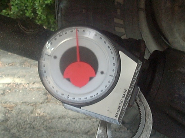
| Pinion Angle: 68° | Driveshaft Angle: 23° |
- For a double-cardan driveshaft, you really do need to work with angles directly, that is you need to know the angle of the driveshaft itself and of the u-joint at the end opposite the CV joint.
-
How do you measure the angle of the drive shaft itself?
-
I use a Stanley digital carpenter's level (reads angles to nearest
0.1°), taking the sensing unit out of the carpenter's level
housing. This level has a mode to read out in degrees. First, measure
the angle of the drive shaft on the vehicle at rest. Then remove the
drive shaft and place the level on the flanges it was attached to and
get those angles.
- Tip: if you do this, you don't need to use the technique in step 1 above.
- Then subtract the drive shaft angle from the average of the two flange angles and that your static operating angle.
- An alternate way to get this measurement is to measure the distance to the ground at both ends of the drive shaft and the distance between the two measured points and simple trigonometry (you do remember your trig, right?) will get you the slope, then you need a guesstimate of the actual flange angles. The transfer case flange is tilted down from vertical a few degrees on my truck.
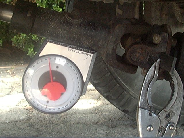
- You can also get a simple, inexpensive angle finder (this one is $5.99), one with a magnetic base is nice for attaching to the driveshaft. It should read to within 1° or so:
-
I use a Stanley digital carpenter's level (reads angles to nearest
0.1°), taking the sensing unit out of the carpenter's level
housing. This level has a mode to read out in degrees. First, measure
the angle of the drive shaft on the vehicle at rest. Then remove the
drive shaft and place the level on the flanges it was attached to and
get those angles.
-
Above, you can see how I measured the pinion flange angle, I clamped a
piece of flat bar to the flange and placed the angle finder on it,
gauge reads 68° which is equal to 22° from vertical (i.e. 90
- 68 = 22). The driveshaft angle is 23° (from horizontal). The
difference in the to angles is 23° - 22° = 1°, meaning
the pinion is 1° below the angle of the driveshaft.
- One point to note is that my driveshaft doesn't really run at 23°, the above pictures and measurements were done on my sloping driveway, its about 8°, but it really doesn't matter, you don't need to be on a perfectly flat and level surface to do these measurements. Whatever angle the surface you are on is canceled out, you only care about the difference of the two angles, not their actual values.
-
If you have a double cardan drive
shaft, you want the end with the single
cardan joint to be at right angles to the drive shaft itself.
So, get the drive shaft slope and set the pinion flange to be at a
right angle to it.
- So determine the exact angle, find your driveshaft angle from horizontal and then set the pinion flange to the same angle from vertical
-
You may need to repeat this process a time or two if starting from
scratch. As you tilt the pinion up, the distance the driveshaft has to
drop from the transfer case is decreased, making the angle a bit less
than measured un-tilted.
- For example, when I installed new springs on my Toyota 4Runner, I decided to use a CV-style rear driveshaft. I used 3.5" longer than stock rear spring shackles to accommodate the longer springs, this gave me about 6° of tilt, but I measured and determined I needed an additional 8° of angle. After installing the 8° shim, I found the pinion is now tilted up a bit more than the driveshaft. I therefore designed my own steel shim at 5° to set the pinion 1°- 2° below the driveshaft angle to correct that problem.
- What I didn't account for with the double-cardan setup is that as you tilt up the pinion, you are raising the pinion end of the driveshaft and thereby decreasing its angle.
- I assumed this would be negligible, but I was wrong.
- On my axle (a Toyota mini-truck axle, 8" ring gear), it is approx. 11" from the axle centerline to the pinion flange. If my driveshaft is about 44" long, then there is an inverse ratio of the respective lengths to the angle change. In this case, for every 4° of pinion change, there is 1° of driveshaft change.
- In other words, if you need a 5° angle change, move the pinion up 4° and this will drop the driveshaft angle 1°.
-
If you have a single-cardan driveshaft and want to install longer (or
shorter) spring shackles, you can determine the angle change quite
easily. Just by knowing how much longer (or shorter) the spring
shackles are compared to stock and the length of the spring, simple
geometry will tell you the angle change. For example, on a Chevy 1500
2WD pickup, with 65" long rear springs, and with a shackle 3"
longer than stock, divide the added shackle length by the spring length
(3/65) and use the Inverse-Sin trig. function on a calculator to
determine the angle. Using the Windows calculator, enter the following
3
    / 65 Inv Sin
and see the answer is 2.7°. In this case, a 3° shim is about what is needed to correct the angle change brought about by the 3" longer than stock shackle.
So, why must you run the u-joint at 0° with a CV joint on the other end. See the discussion above and realize that the only time a single u-joint can operate smoothly is at a 0° operating angle. At any non-zero angle, the u-joint will induce a rotational vibration in whatever it is hooked to. This is not desirable, so the u-joint MUST be at 0° operating angle in a CV- or double-cardan type shaft. In theory, 0° is ideal as far as the vibration end of things go, having a u-joint actually running at exactly 0° is not good from a practical mechanical standpoint. Why is that? Will, inside the ends of the u-joint cross are tiny needle bearings and if you run the joint at exactly 0° those needle bearings never move and thus the concentrated force of the bearings on the races sits in one spot and you can encounter "brinelling", which occurs when the bearings create dents in the races, creating an effect like a flat spot on a tire. So a slight operating angle of 0.5° up to 1° or so will let the bearings roll back and forth over a larger area of the races and also ensure that grease can be moved around over the bearings, since with no relative motion, the grease will not flow.
Advantages of a double-cardan or CV drive shaft is that it can run smoother at higher angles that a single-cardan shaft. It shares a downside of the alternate single-cardan shaft alignment above, in that is is sensitive to ride height changes. For example with a ~48" long drive shaft, ever inch of ride height change will make about a 1° change in the angle of the drive shaft and thus a 1° change in the angle of the lower u-joint. So in a vehicle that carries a varying amount of cargo, you may need to find a compromise of the loaded and unloaded shaft angles. Also, the pinion angle is tipped up higher than with a traditional u-joint shaft alignment, but not as far as with the alternative u-joint alignment.
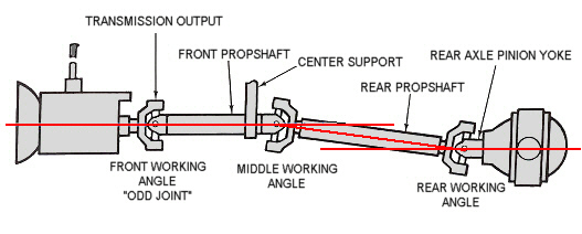
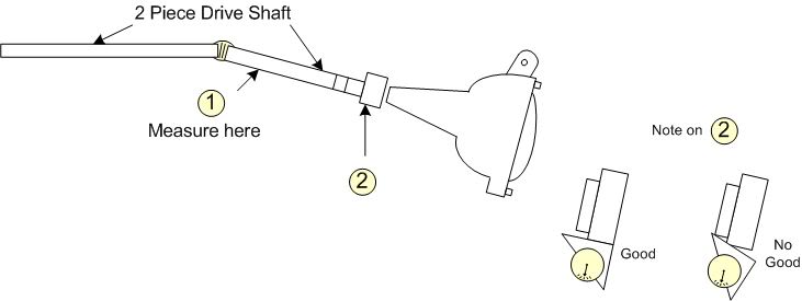
2-Piece Drive Shafts:
2-piece shafts are becoming popular with light truck makers. Their main advantage is that can be lighter for a given length due to the center support bearing (CSB) splitting the shaft into 2 sections. Also, if set up properly a 2-piece shaft can run smoothly. But the main disadvantage of a 2-piece shaft is they are affected negatively by almost any modification to the suspension. Lift or lower the truck and vibrations are likely. Some folks try adding spacers on the CSB to raise or lower it. But often this causes more problems that it solves. It's important to think about a 2-piece shaft as 2 separate drive shafts. There's the section from the transmission/transfer case to the CSB. This section of the shaft is typically unaffected by changes in ride height. However, the lower section of the shaft is affected. The main problem is that few, if any, truck mfgs. have any specifications on what the shaft alignment should be or how the shaft was set up at the factory. Hopefully you measured all the shaft and joint angles and lengths before you modified the suspension. One common issue on 2-piece shafts is that the CSB gets pulled out of it's housing because the shaft is too short and needs to be lengthened. See this page for drive shaft spacers...
Below are two common 2-piece drive shaft configurations. They are basically the ame overall setup in that there are 3 u-joints and the center support bearing. But the difference lies in how the angles are distributed over the 3 u-joints. With 2 u-joints, as we saw above, 2 opposing u-joints need to run and the same operating angle for minimal vibration. With 3 u-joints, you generally have that same setup, 2 of the 3 are at the same angle. And then the remaning u-joint must be running at 0 degrees in order that it also run smoothly. Another option is to have all 3 u-joints at the same operating angle.
What varies in which 2 u-joints are at the same angle and which is at 0 degrees. The key in diagnosing vibration issues in these types of shaft is determining which configuration you are dealing with. We have diagrams of 4 common setups are shown below. There are other setups possible as well. For example, the center u-joint might be replaced with a CV or double-cardan joint.
Here's a good article on 2-piece drive shaft setup: http://www.hotrod.com/articles/0608rc-driveshaft-tech/
If we label the u-joint operating angles with A as the upper, B as the middle and C as the lower, any of the following 4 relationships work:
- A = 0, B = C
- A = C, B = 0
- A + B + C = 0, A=B=C or A-B = B-C, depending on the source
- A = B, C = 0
Style 1 has an advantage of being insensitive to ride height variations, either due to loading or spring or block suspension lifts, since the lower 2 u-joints will stay aligned as the axle moves closer to or farther from the frame.
Style 2 sets the middle angle to 0 and functionaly turns the 2-piece shaft into a 1-piece shaft.
Style 3 involves "juggling" the operating angles of the 3 u-joints to net a zero total. This is an option if you are unable to get any single u-joint close enough to 0° to "eliminate" it. This can also be set up with all the angles being "equal" in magnitude but opposite "sign".
Style 4 is somewhat like a CV or double cardan type shaft. All the shaft angle is handled by the upper pair of u-joints.
Styles 2, 3 and 4 will be sensitive to ride height variations since the lower u-joint and shaft angle may change as the axle position changes.
So as you can see, each style has advantages and disadvantages. Your vehicle may have been set up in one style and after a suspension height change, you may have vibration issues. You'll need to see which setup style is the easiest one to target as you bring everything back into alignment. That might be the original style, or it may be easier to set things up in another style.
1: 2-Piece shaft with 0 angle upper u-joint
In this case, you want to keep the front of "odd" u-joint angle at 0 degrees and only adjust the axle and pinion u-joint operating angle to match that of the middle u-joint.
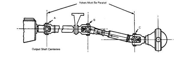
2: 2-Piece shaft with upper and lower u-joints parallel
In this case, you are trying to get the upper and lower u-joint angles parallel to each other. Note that the sketch is a bit misleading as you may need to have the middle u-joint at a 0 degree operating angle.
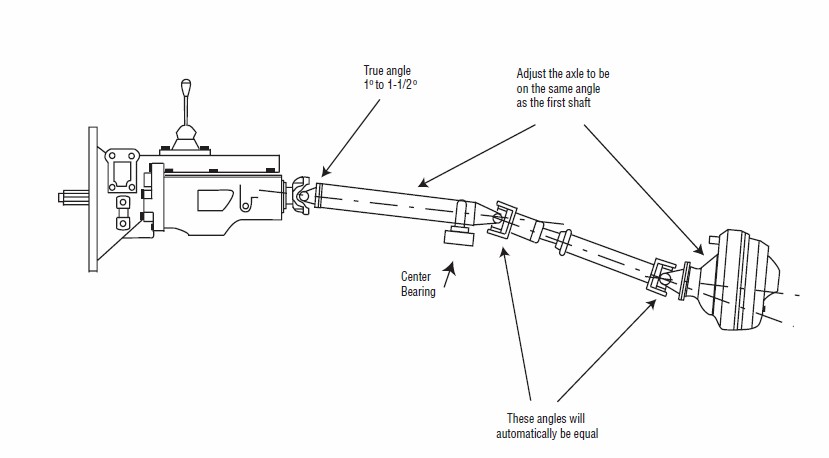
3: 2-Piece shaft with different angle shaft sections
In this case you are basically spliiting up the overall shaft angle between the trasnmission and the axle. This gives you two shorter shafts connected end to end and each one is set up with different operating angles on each u-joint. With this type of setup, you may need to adjust both the pinion angle at the axle as well as the angle/height of the center support bearing. This will likely take a piece-wise process, adjusting the pinion angle, measuring and adjusting the center support bearing, etc. An example might be setting the upper joint angle to 2° down and then the center joint to 2° + 2° = 4° down below the upper shaft angle. Then set the lower angle to 2° up. This would net a 0° sum of operating angles. However, since the u-joint velocity cancellation is not linear with angle changes, you'll likey need to modify say the lower joint angle a bit to compensate. U-joint angles and alignments are best approximated with the cosine of the operating angle. If you recall your high school trig identities, regarding adding the cos of angle "a" and the cosine of angle "b" you get cos(a) + cos(b) = 1/2 x (cos(a-b) + cos(a+b)). So 2+2 might not equal 4 exactly, likely pretty close at smaller angles, but as the angles increase, the difference increases.
Another way of looking at this is that the angles A and B roughly cancel each other out and angles B and C do likewise. This can happen if angle B is twice angle A (in absolute terms or it's the same as A relative to A). Then angle C is set up to cancel out angle B on the lower part of the shaft. Thus the difference between angles A and B is the same as the difference betweenh B and C.
4: 2-Piece shaft with 0 angle on lower u-joint
In this case the upper 2 u-joints are at the same operating angle and the lower u-joint at the axle is at 0 degrees. Not shown is the upper u-joint (off to the left) and the CSBwhich would be just left of the center joint. With this type of setup, you may need to adjust both the pinion angle at the axle as well as the angle/height of the center support bearing. This will likely take a piece-wise process, adjusting the pinion angle, measuring and adjusting the center support bearing, etc. Note that you'll likely have the upper joint and section of shaft angled down at some angle. Then the center joint will be angled down that same amount such that the lower section of shaft is at twice the angle as the upper section of shaft. For example, upper joint and shaft angled down 2°, center joint angled down 2° below that and the lower section of shaft angled down 4°.
Here's a writeup on setting up the angles on a Toyota Tacoma with CSB where the upper shaft section u-joints are at equal angles and the pinion u-joint is at 0 degrees:
Phasing:
Phasing is a term that describes the alignment of the single-cardan joints on opposite ends of the drive shaft. As discussed above, a single-cardan (or u-) joint does not rotate at a constant velocity if the operating angle is non-zero. The drive shaft speeds up and slows down slightly as it rotates due to the nature of the joint. One way to reduce this is to make sure the joints at each end of the drive shaft are aligned properly. If the yokes on each end of the shaft line up with each other, as seen indicated by the light blue line in the figure below:
Then the affect will be that the two joints will tend to cancel out the speed variations from each other. In most 4x4 applications, the drive shaft will have a slip yoke in the middle to allow for changes in length. If the shaft is ever taken apart, it is important to get it re-aligned properly when it is re-assembled. One way to do this is to mark both sides of the slip yoke. However, you should check that the joints really do align properly, don't assume they are. The reason for the phasing is that the speed variation of the joint is related to its operating angle and its angle of rotation. In order to get the most effective cancellation, the joint yokes *must* be aligned exactly with each other and the operating angles must be identical. Any variation in either angle will show up as uncanceled vibration. While unequal operating angles result in a vibration that increases with shaft RPM, phasing problems may be felt at lower RPMs and higher loads, like when accelerating from a stop.
Most driveshafts will have some sort of alignment mark stamped or painted on to indicate the proper orientation of the slip yoke. If there is none, they try lining up the u-joint end caps as close as possible. One trick that can sometimes help with phasing is to spin half of the driveshaft 180° before re-installing it to see if this makes any difference. Often one orientation may balance out better than the other. Once you find the proper alignment, paint a mark on both sides of the slip yoke so that you can get it back together correctly next time.
For a double cardan driveshaft, phasing is not an issue, although you may want to try and line up the bearing caps anyway.
![]()
Fixing Driveline Problems:
Most likely, if you've read this far (or even searched for this page) you may have a problem with driveline vibration or noise. The fundamental rule of drive shafts is that they vibrate unless some basic conditions apply, such as they run at a dead flat angle and are perfectly balanced and of sufficient diameter and wall thickness to prevent whipping at high speed.
The first step is to characterize the vibration, figure out when it happens, when it gets better and worse, etc.
-
Vibrations at relatively low speed (under ~30 MPH) are often due to
mechanical issues such as:
- Phasing
- Alignment
-
Straightness, either due to a new shaft not being built straight or a
used shaft being bent.
- You would need a dial indicator to measure such radial run-out and that would probably best be done at a drive line shop, because after straightening, the shaft will likely need to be balanced as well.
- Could also be due to a u-joint not being installed properly or a drive shaft flange not fitting properly causing the shaft to not line up with the output shaft or pinion gear.
- And realize that drive shafts are typically straightened by use of heat and cold. The drive line shop will use a torch to heat one side of the shaft, expanding the steel on that side, while cooling the opposite side with a wet rag to shrink the steel there to pull a shaft back into straightness. That said, any application of sufficiently high heat can case shaft to lose straightness.
-
Vibrations at relatively high speeds are often due to balance problems.
- These vibrations may come and go as speed increases as you move in and out of resonant frequencies of the drive shaft.
-
Vibrations that get worse when transitioning from acceleration to
coasting to deceleration, like when you back off the gas over the top
of a hill and before you go into full on engine braking, may be due to
loose or worn parts, like loose flange bolts, worn or over-extended
slip yoke, etc.
- A slip yoke typccally consists of a male and female spline section that allows for the shaft length to change as the suspension moves.
- The more the splnes are pulled apart, the looser the fit will be. At some point, that may allow vibrations to "escape" from the shaft.
- Lengthening the shaft is one solution or it may be possible to add a drive shaft spacer to extend the shaft.
-
Vibrations that get worse say going uphill or accelerating at speed
than when going the same speed on the flat or downhill, or vice versa,
might be due to a slight alignment issue.
- If worse uphill/accelerating, the lower u-joint angle may be moving too high as the axle and pinion tip up under load, if so, tip the static pinion angle down a little lower than it is now.
- If worse downhill/decelerating, the lower u-joint angle may be moving too low as the axle and pinion tip down from the lessened load, if so, tip the static pinion angle up a little higher than it is now.
-
Vibrations at very high speeds may be due to approaching the drive
shaft critical speed, which is essentially the resonant
point where the shaft begins to whip and vibrate violently.
- In this case, only a new driveshaft design will help, changing material, tubing diameter or wall thickness, etc.
- These sorts of RPM limits are usually up in the 8000-10,000 RPM range, so typically only seen in race vehicles.
If you suspect vibration in the rear driveshaft, one way to isolate the cause of the problem is to remove the rear shaft, lock in the front hubs and test drive in 4H (basically Front Wheel Drive), assuming your transfer case and 4WD system allow this mode of operation. If the vibrations remain, you've just eliminated the rear shaft as the cause of the problem, its likely to be a bad bearing, bent axle, out of round (or balance) wheel/tire, or something in the engine or transmission. If the vibrations go away with the rear shaft removal, then its something in the rear drivetrain that is the cause, the transfer case output, rear shaft (and center bering if present), the single and/or double cardan joints, the pinion bearing and rear differential could all be the cause.
If so, you probably want to fix it. How to fix it depends somewhat on what led to the problem in the first place.
-
If your drive shaft is has been damaged off-road (bent or dented) then
this can cause vibration as well, a common problem is that the small
balancing weights on the shaft can get scraped off on an obstacle).
- If the shaft is damaged, it should be fixed. Typical cost for a straighten/balance is about $60.
-
If any of the joints or slip yokes are worn (i.e. if you can feel any
play in any part of the shaft by hand) this should also be fixed.
- For slightly loose joints, try greasing the joint well and see if it (temporarily) fixes the looseness and vibration.
-
For a loose slip yoke, you can try injecting grease at the grease
fitting, but take note of where the fitting is relative to the splines
of the yoke.
- If you don't feel the fitting will get grease to the shaft spline area, mark the shaft alignment, separate the slip yoke and use a brush to paint grease onto the male splines and then re-install it, lining up the phasing marks.
-
If greasing the slip yoke temporarily helps with the vibration, that is
a clue that you are on the right track. It may be that your drive shaft
has simply been stretched too long and the splines are not engaging
fully or if it has run a long time at that position, the splines may
have worn in that position.
- In both these cases, a changing the drive shaft length, with a spacer or by re-tubing it, you can get more spline engagement or a new section of male and female splines engaged that may tighten it up.
- If that does not help, a new slip yoke may be needed.
- Loose parts tend to vibrate under no-load conditions, like at speed when you just back off the gas pedal and are just coasting without engine braking. With no load, any loose part will make any vibration feel more apparent. And realize that almost all drive shafts w/ u-joints vibrate while moving even if perfectly balanced and aligned (it is perfectly normal), but if everything is tight, the vibration will be absorbed by the torsional stiffness of the shaft itself. But if there is a loose part, that will let the vibration be felt outside the shaft.
-
Check the transfer case and pinion flanges for tightness.
- If they can be moved side to side by hand, they may need to be re-tightened or their bearings may be going.
- And don't forget to check the dust shields that are pressed onto the back side of the flanges. Those can sometimes work loose and vibrate/make noise and lead to you think you have a "real" vibration problem, but may not.
- If you recently lifted (or lowered) your vehicle's suspension by changing springs, adding blocks or spacers, or changed spring shackles, all these can affect the driveline angles, which in turn can lead to vibration...
Assuming there is no physical damage or worn out parts, and you simply have an angularity problem, there are a number of ways to fix it. Basically, you want to correct the angles. How you do that depends on a number of factors:
- How the angles got off in the first place
- How bad the angles are, especially if the operating angle is greater than 10°
- The type of driveshaft you currently have
- What kind of suspension you have
- How much work you want to do to correct the problem :-)
If you have a multi-link suspension, perhaps with coil springs, there are a few options. If the links are adjustable, you should be able to correct the angles with the adjustments. If no adjustments are provided, then you'll either have to get an adjustable link or relocate the suspension brackets on the axle.
If you have a leaf-spring suspension, then there are more options available. Among the options are shims, rotated spring perches, longer or shorter spring shackles, or driveline changes. Below is a table of common lifts and driveline affects:
| Type of Lift / Driveshaft & Location |
Single Cardan Rear |
Single Cardan Frnt/Fwd(1) |
Single Cardan Frnt/Rev(2) |
Double Cardan Rear |
Double Cardan Frnt/Fwd(1) |
Double Cardan Frnt/Rev(2) |
| Spring | None | None | None | Tilt UP | Tilt UP | Tilt UP |
| Block | None | None | None | Tilt UP | Tilt UP | Tilt UP |
| Shackle | Tilt DOWN | Tilt DOWN | Tilt UP | None(3) | None(3) | Tilt UP |
Notes:
- Front axle with shackles forward
- Front axle with shackles reversed
- Affect varies with length of spring, shackle and driveshaft length
Installing a shim between the axle and spring is the easiest way to correct the driveshaft angle (here's a convenient on-line source for custom-built axle shims). But which way does the shim go in to fix the problem? It depends on the spring and axle configuration, namely Spring-Over-Axle (SOA) or Spring-Under-Axle (SUA). The following table summarizes the direction of pinion tilt vs. axle configuration. and which way the "fat end" of the shim faces:
| Tilt/Config | Front/SUA | Front/SOA | Rear/SUA | Rear/SOA |
| UP | Backward | Forward | Forward | Backward |
| DOWN | Forward | Backward | Backward | Forward |
Its best to visualize the spring as fixed flat surface under the vehicle. Then the shim will sit between the spring (top or bottom) and the axle, which then must rotate up or down to align the spring perch of the axle with the angle of the shim.
Conclusion:
And, a final thought on driveline vibration is that you need to think of the entire drive line as a system. It is not just a single angle or single piece of tubing or a single u-joint, etc. You have the shaft itself, 2 or more joints (single- or double-cardan), perhaps a center support bearing and then some sort of output spline or flange driving the shaft from the transmission or transfer case and a similar flange at the pinion gear on the differential. You might find an angle is off, fix that and find that the vibration is still present. It is likely that with the angle being off, that induced vibration in the shaft that led to the u-joint(s) wearing out. So you replace the u-joint(s) and find the vibration is still there. It might be the case that the pinion shaft flange was loosened up by the vibration of the misalignment and/or the worn u-joint, etc. So the point is that you need to get the entire drive line all corrected/fixed at the same time to make it run smoothly as a system. So don't be put off if you find one issue, fix that and find that the problem is still there. You may have fixed the root cause of the problem, but now have other secondary issues (like worn u-joints or loose flanges) that need to be replaced/tightened as well.
![]()
Technical References:
Here's a handy right triangle calculator. Here's some example calculations based upon a driveshaft between two flanges that are 40 inches apart horizontally (length b) with different vertical separation (length a), using the angle/length labels in the above calculator. In this example, assume the change in vertical drop is the lift height. That is, 6 inches might be the stock drop and 9 inches would be the case with a 3 inch suspension lift (9 - 6 = 3). Then the change in shaft angle and length for a given lift or ride height change is shown. You'll of course want to use the measurements off your own vehicle. The change in angle can help in selecting a pinion correction shim and the change in length could help in selecting a spacer for lengthening the drive shaft. For example with a 4 inch lift, a 3/4 inch spacer (just shorter than 0.8 inches) would be ideal to correct the length change due to the lift.
| Vertical Drop (a) | Shaft Angle (A) | Shaft Length (C) | Change in angle | Change in length |
| 10.0 | 14.0 | 41.2 | +5.4 | +0.8 |
| 9.0 | 12.7 | 41.0 | +4.1 | +0.6 |
| 8.0 | 11.3 | 40.8 | +2.7 | +0.4 |
| 7.0 | 9.9 | 40.6 | +1.3 | +0.0 |
| 6.0 | 8.6 | 40.4 | +0.0 | +0.0 |
- Spicer On-line Angle Calculator
- Dana/Spicer Driveline Installation information (PDF)
- In Depth Tutorials and Information on U-joints and various CV joint designs
- 4x4 Wire's Driveline Basics article is well written
- Tom Wood has an excellent Tech Information section
- Billa Vista's Driveshaft 401 page is also a good technical reference
- Excellent video on rebuilding a Toyota double-cardan/CV joint
-
Here's a
write-up on using laser pointers for driveshaft alignments:
-
Ben
Lee has a nice write-up of his driveline fixes and some alternate drive
shaft geometries
- This alignment style is also known as a W Configuration or Arrangement.
Driveshaft sources:
- Angle Correction Shims:
- Nationwide/USA:
-
SF Bay Area, CA. USA
- I used to use Driveline Service of San Jose for all my driveshaft needs, before they closed the local shop
- South Bay Driveline is another shop in my area, Steve builds great shafts too, Steve made an awesome rear CV shaft for my 4Runner a few years ago.
Author: Roger Brown  ===>>
===>> 
[Last updated: 23.June.2026 ]
Visitor # since 28.AUG.2001