Toyota 4Runner/Pickup Technical Information
Here's various bits and pieces of technical specifications, etc. that I've collected about my 1985 (1st generation) 4Runner:
| Dimensions | Steering | Engine | Drivertrain |
| Differentials | Fluids | Shell | Electrical |
| Suspension | VIN | EFI | Wheels/Tires |
[Return to main 4Runner page]
![]()
Dimensions:
| Length | 174.6" |
| Width | 66.5" |
| Height | 66.1 (stock) ~72" (lifted) |
| Wheelbase | 103" stock 106" w/ rear spring swap and dropped spring hanger |
| Tread (Track) | 55.9" (F) 55.1" (R) |
| GVWR | 4800 lb. |
| Cargo | 700 lb. |
| Fuel Tank | 17.2 gallons |
| Wheels | 15x6J / 3-3/8" backspace |
| Tires | 225/75R/15 (~28x9) |
- Notes:
-
4Runner has the same frame dimensions as the std. cab pickup of the
same vintage
- The early Xtra cab and long bed pickups are ~113" wheel base
- Click here for a scan of the FSM frame dimension drawing
- Factory paint color codes
- In California, being above 4500 GVWR and as long as registered VA (various) or PK (pickup) this model is good for a ground-frame height of 27"
- The early Xtra cab and long bed pickups are ~113" wheel base
![]()
Steering:
| Toe In | 1mm ± 2mm |
| Camber | 1°45'± 45' |
| Caster | 2°00' ± 1° 4Runner 2°15' ± 1° pickup |
| Steering Axis Inclination | 9°30' ± 45' |
| Turning Angle: Max Angle | Inside: 30°30' Outside: 29° |
| Turning Angle @20° Outside | Inside: 20°30' |
![]()
Engine:

| Model | 22R-EC |
| Bore | 92mm |
| Stroke | 89mm |
| Displacement | 2366cc |
| Power | 116 HP @ 4800 RPM |
| Torque | 140 lb-ft @ 2800 RPM |
| Compression | 9.2: 1 |
| Fuel | 87 Octane |
| Cam | Intake Duration |
Exhaust Duration |
Intake Lift |
Exhaust Lift |
| 22R | 272° | 248° | 10.1mm | 9.7mm |
| 22RE | 248° | 280° | 10.0mm | 9.7mm |
Notes:
- ECU p/n: 89661-35020 (the '86/'87 ECU seems to work as well, 89661-35070)
- Thermostat info:
- Off-Road.com has an excellent page on 4-cylinder Toyota engines
-
This is a neat site with a Java-based torque
curve synthesizer:
- Here's the computed Torque Curve for a 22-RE engine
![]()
Transmission/Transfer Case(s):

The Aisin Seiki W56 is a five-speed, fully-synchronized manual transmission is found in Toyota 4x4's with the 22R-E engine:
| Gear | Ratio |
| 1st | 3.954 |
| 2nd | 2.141 |
| 3rd | 1.384 |
| 4th | 1.000 |
| 5th | 0.850 |
Or the A340F 4-speed automatic transmission:
| Gear | Ratio |
| 1 | 2.80 |
| 2 | 1.52 |
| 3 | 1.00 |
| 4/OD | 0.71 |
The Aisin Seiki RF1A two-speed transfer case is found in Toyota 4x4's:
| Gear | Ratio |
| Hi | 1.00 |
| Lo | 2.28 |
With a Marlin Ultimate Crawler (dual transfer case), 5.29:1 R&P gears, overall crawl ratios work out to:
| Front | Rear | 1st | 2nd | 3rd | 4th | 5th |
| 1.00:1 | 1.00:1 | 20.9 | 11.3 | 7.3 | 5.3 | 4.5 |
| 2.28:1 | 1.00:1 | 47.7 | 25.8 | 16.7 | 12.1 | 10.2 |
| 1.00:1 | 4.70:1 | 98.3 | 53.2 | 34.4 | 24.9 | 21.1 |
| 2.28:1 | 4.70:1 | 224.1 | 121.4 | 78.5 | 56.7 | 48.1 |
With a Marlin Ultimate Crawler (dual transfer case), 4.88:1 R&P gears, overall crawl ratios work out to:
| Front | Rear | 1st | 2nd | 3rd | 4th | 5th |
| 1.00:1 | 1.00:1 | 19.3 | 10.4 | 6.8 | 4.9 | 4.1 |
| 2.28:1 | 1.00:1 | 44.0 | 23.8 | 15.4 | 11.1 | 9.5 |
| 1.00:1 | 4.70:1 | 90.7 | 49.1 | 31.7 | 22.9 | 19.5 |
| 2.28:1 | 4.70:1 | 206.8 | 112.0 | 72.4 | 52.3 | 44.4 |
Notes:
- To put this in perspective, take a typical engine idle speed of 800 RPM and using 33" tires with the above gearing, your speed is about 29 feet/minute, or less than 1/3 MPH!
- FYI: My 22RE engine will stall in lo-lo-2nd gear at idle (121:1) but will not stall in lo-lo-1st (224:1), even up a steep hill w/ brakes applied.
- The Marlin Crawler web page has lots of Toyota gearing information
- Here's a nifty gear ratio calculator
- Four Wheeler's transmission page has info on lots of other trannys
- The 4x4now page entitled "Innovations in Four Wheel Drive/All Wheel Drive Systems" covers a lot of ground
![]()
Differentials:
Below is some information on the 8" Toyoya 3rd members/differentials:
Ratios:
Here is a table of ring and pinion sizes for various gear ratios in the Toyota 8" differential:
(typical axle ratios for manual transmission equipped trucks, 28" stock tires)
| Ratio | Ring | Pinion | Factory Color Code |
Crawl Ratio (stock) |
Tire Size to stock M/T |
Tire Size in use M/T |
Tire Size to stock A/T |
Tire Size in use A/T |
| 3.42 | 41 | 12 | Purple | 31 : 1 | . | . | . | . |
| 3.90 | 39 | 10 | none | 36 : 1 | . | . | . | . |
| 3.93 | . | . | none | . | . | . | . | . |
| 4.10 | 41 | 10 | Pink | 37 : 1 | 28 | 28 | . | 28 |
| 4.11 | 37 | 9 | Orange | 37:1 pre-'82 | 28 | 28 | . | 28 |
| 4.30 | . | . | Blue | . | 29-30 | 29-30 | 28 | 28 |
| 4.37 | 35 | 8 | Green | 40 : 1 | 30 | 29-30 | 28 | 28 |
| 4.56 | 41 | 9 | Yellow | 41 : 1 | 31 | 29-31 | 29-30 | 29-30 |
| 4.88 | 39 | 8 | White | 44 : 1 | 33 | 31-33 | 31 | 31-33 |
| 5.29 | 37 | 7 | none | 48 : 1 | 36 | 33-36 | 33 | 33 |
| 5.71 | 40 | 7 | none | 51 : 1 | 39 | 37+ | 35 | 33+ |
There are 4 common factory gear ratios for the '84-'95 pickups and 4Runners. What ratio your truck has depends on what type of transmission it came with (manual/4 speed) or automatic) and whether it came with the factory 31" tire option (early '90s SR5 option) or the normal 28" (P22575R15) tires, as noted below:
| Tranny/Tire | 28" | 31" |
| Manual | 4.10 | 4.56 |
| Automatic | 4.30 | 4.88 |
How to determine what ratio you have:
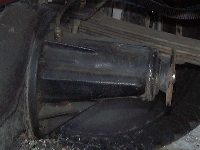
You can look up the factory axle code for a given vehicle using this table. Or refer to the paint code on the end of the pinion flange shaft, as shown in the image below:
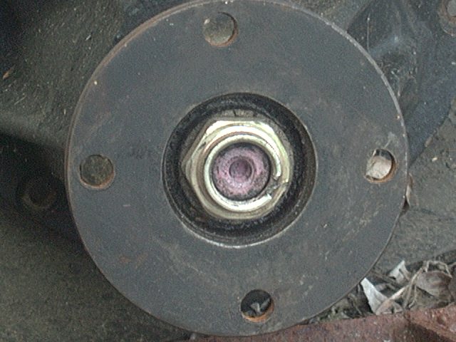
Note that the color codes above are not an absolute way to determine gear ratio, nor is the vehicle's model info/VIN sticker. However, if you have an axle/differential off of an unknown vehicle or it has aftermarket gears, then you'll need to determine the ratio. If the differential is out, count the ring and pinion gear teeth (or that data is often stamped into the ring gear).
If the differential is still installed inside an axle, then assuming you have open differentials, lift one wheel on the axle in question off the ground. Put the tranny in neutral, transfer case in 2H, e-brake off (if is the rear axle you are testing) and put a chalk mark on the driveshaft and on the tire. Now turn the tire in the air through 2 full revolutions, while counting the revolutions that the driveshaft makes. The number of which will be equal to your gear ratio. You can get a more accurate count by doing 10 or 20 wheel revolutions and dividing the driveshaft turns accordingly.
- Why 2 wheel revolutions?
- Because, the ring gear in an open differential turns at the average speed of the two axle shafts connected to it. Since one is on the ground (and thus not turning) the other axle shaft (i.e. the one you are turning) must turn twice as fast as the ring gear, so 2 revolutions on one axle + 0 revolutions on the other shaft averages out to 1 revolution on the ring gear.
If you have a limited slip or automatic locker, then you'll need both wheels in the air and you'll use just one wheel revolution to get the rear ratio. For better accuracy, you can use say 10 (or 20) revolutions and then divide your drive shaft revolutions to get the gear ratio. For example, the difference between 4.56 (a little over 4-1/2 revs) and 4.88 (a little over 4-3/4 revs) might be hard to distinguish, but if you did 10 times as many revs on the wheel, you magnify the difference at the driveshaft by 10 as well. So instead of say 0.32 revolution difference (4.88-4.56), you would now have 3.2 revolutions difference if turning the wheel 10 (or 20) times.
Note that you may get different readings on the gear ratio with the above methods. Least reliable method is likely the "paint code". Next up the list in reliability is the vehicle VIN plate. It should be accurate given the diff in the vehicle is still the original one or that you know that VIN info from the vehicle the diff came out of. The wheel spinning technique should give good information with good technique. But it can give you misleading information, too. I once tested a diff I had and it seemed to do right at 4.5 axle shaft rotations for 1 pinion rotation. Fugured it was a 4.56 until I counted the teeth and found it to be a 4.10. So a tooth count is the most accurate test, but also the hardest to do if the diff is bolted up to the axle housing.
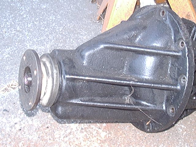
Types of Toyota 8" 3rd Members
 |
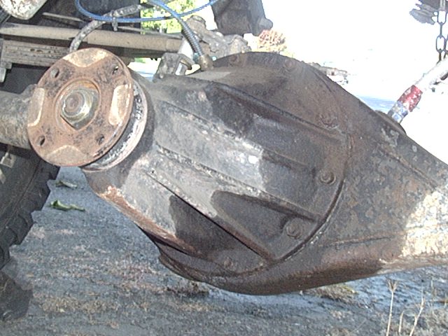 |
| 4Cyl/8" | V6/8" |
 |
. |
| HighPinion/8" | . |
Above are photos of the various Toyota 8" 3rd member housings. All the housings are interchaneable in that the mounting studs and axle splines are identical. The 4 cyl differential internals are different than the V6 and High Pinion, so that lockers and limited slips are different. The 4 cyl ring and pinion gears are somewhat smaller overall than the V6 parts, i.e. the ring gear is thinner and the pinion gear and bearing are less substantial. The 4- and 6-cyl housings can be distinguised by the number and style of reinforcing ribs present.
The 4- and 6-cyl housings may be used in rear or front applications. The pinion (or companion) flange nut takes a 30mm socket.
The High Pinion diff uses reverse cut gears and is best suited for front solid axle applications. While it shares internals with the V6 diff, the gears are unique to the High Pinion due to the reverse cut, which puts the gears on the drive side of the teeth in the front axle. High pinion diffs are commonly found in 1990-1997 FJ-80 and FJZ-80 model Landcruisers that had the solid front axles. Ironically, the high pinion diff was not designed for the added ground clearance, but rather so that the steering tie rod on the FJ-80 could be run *below* the front driveshaft to keep the vehicle low!
Reverse Cut vs. Standard Cut
Perhaps the single most misunderstood axle term is reverse cut, often mistakenly referred to as reverse rotation. A reverse cut housing is not standard cut housing turned upside down, it is a specially designed housing, most notably with internal mechanisms to aide in pumping gear oil up to the high-mounted pinion gear and bearings for proper lubrication. The term "reverse cut" refers to the direction of the spiral cut in the ring gear, which is opposite that of a standard cut ring gear. Contrary to popular belief, it does not run backwards or in reverse. The principle behind a reverse cut is to strengthen the operation of the gear when it is used for a front driving axle application. See below for an illustration of the ring gear tooth nomenclature and construction. As you can see, the drive side of the gear tooth is nearly perpendicular to the direction that the pinion gear tooth pushes on it, making for an efficient transfer of force. The coast side on the other had, is angled away from the direction of force, this causes the pinion gear to want to "ride up" on the ring gear teeth under load, lessening the area of contact and moving it out towards the thinner ends of the teeth vs. the thicker root of the tooth. As such, it is generally the case that a ring/pinion gear set is 30% weaker when run in the reverse direction. This is not normally a problem, as you rarely see the kinds of loads in reverse that you see when going forward. Likewise, a front axle usually has less load on it that a rear axle, like when climbing up some steep obstacle (i.e. less weight and traction up front) so its common to run a rear differential in a front axle. The 4- and 6-cyl gears will run on the coast side in the front axle, likewise, a high-pinion, reverse-cut differential will run on the coast side in a rear axle application. While the 30% strength reduction sounds like a major design problem, it should really be looked at from the standpoint of an perfectly symmetrical gear tooth. In this case, using the non-symmetrical tooth geometry gives a gear that is 15% stronger in the forward direction and 15% weaker in the reverse direction. While 15% one way or the other doesn't sound like a lot, its enough to make an 8" ring gear, properly cut, as strong as a 9.25" ring gear with symmetrical teeth. However, looking at it the other way of using a reverse cut gear in a rear axle, the 30% strength reduction makes an 8" ring gear only as strong as a 6" gear with normal cut teeth. One way to reduce the load on the gear is to reduce the weight of the vehicle its driving. For example, if the normal cut gear was designed for a 4000 lb. vehicle, reducing the vehicle's weight to under 3000 lbs. will reduce the load on the reverse cut gear in a rear axle to the point it may be strong enough to handle the load.
Other information:
- On-line gear ratio calculator
- Look up which gears are in your Toyota axles
- The 4x4Wire Tech Section has some good writeups on setting up Toyota differentials and lockers
- WJ Markerink's description of traction-aiding differentials
- The Torsen Differential white paper
-
Leif
Pihl has a good page on No Slip Diffs here
- Four Wheeler has a good Axle Spotters Guide on-line
- Eaton has some good video showing various differential combinations on-line
![]()
Fluids:
| Type | Grade | Amount |
| Gasoline | 87 pump octane unleaded (=91 research octane number) |
17.2 gal. |
| Engine Oil | SF/CC, 10W40 | 4.9 qt. |
| Coolant | Ethylene-glycol | 8.9 qt. |
| Manual Transmission | GL-4/5, 75W90 | 22R: 4.1 qt. 22RE: 3.2 qt. |
| Transfer Case | GL-4/5, 75W90 | 1.7 qt. |
| -Dual Transfer Case | GL-4/5, 75W90 | +0.7 qt. |
| Front Differential | Hypoid GL-5, 80W90 | 2.4 qt. |
| Rear Differential | Hypoid GL-5, 80W90 | 2.3 qt. |
| Power Steering | Automatic Transmission Fluid - Dexron or Dexron-II |
~1 qt. |
| Brakes | DOT-3 | ~1 qt |
More Information:
-
Drain/fill plug information:
-
Rear/front differential, transfer case, transmission:
- M18-1.50 thread
- 24mm bolt head (use 6-sided socket only)
- Alternately, 10mm allen head socket on the newer style plugs
-
Engine oil pan:
- M0 thread
- mm bolt head
-
Brake Lines
- M10x1.0 inverted flare fittings
-
Rear/front differential, transfer case, transmission:
- Note that while the transmission oil lists either GL-4 or GL-5 oil, it is best to use GL-4 oil there, it simply works better, makes for faster and smoother shifting (due to the GL-4 oil friction modifiers and the synchro-mesh rings in the transmission). It is "OK" to use GL-5 oil, in that it won't damage anything, but GL-4 oil will work better.
-
In the transfer case, you can use pretty much anything you want, it is
not a synchro-mesh design, so it is OK to use either GL-4 or GL-5 oil.
- Some folks prefer to use GL-4 oil, same as they use in the transmission, just in case the seal between the two leaks and lets the oils mix. If they are the same oil, mixing makes no difference. Some folks choose the more commonly available GL-5 oil, so use what you want.
- In the axles, you *must* use GL-5 oil, it has Extreme Pressure (EP) additives to cope with the demands of the ring and pinion gears.
-
Synthetic vs. conventional gear oil is pretty much up to you.
- I choose to run conventional oil in the engine (changed peroidically) and synthetics in the drive train, since they seem to run cooler, last longer and don't smell as bad as conventional gear oil. My reasoning is that if I can save a gear oil change or two, the added cost of the synthetic oil more than pays for itself.
- Some folks who run a lot of deep water and mud go with conventional gear oils, since they tend to change out gear oil more frequently due to the water getting in.
- Synthetic Gear Oil sources
- Lubrication Theory and Practice by Bruce Bowling (which now appears to be lost - any tips on its location would be appreciated)
- The Engine Oil Bible is another excellent source of lubrication information
- The American Petroleum Institute (API) is the definitive source of oil information.
![]()
Shell:
The 1st generation 4Runners feature a fiberglass shell over the rear seat and cargo area. This shell may be removed and installed with the following procedures. You'll need a 12mm wrench or socket for the shell bolts and a Philips screwdriver for the trim.
Refer to the fastener letter designations in the image below for the removal and installation steps below:
 |
 |
| Shell Fastener Designations | Cover Top Bolts: A below, B-E above |
Removal:
-
Open the rear window fully
- Remove any CB antenna or spare tires on your rear bumper
-
Remove the screws and plastic trim pieces.
- The plastic may be brittle
- Disconnect the wire connector and washer hose (for the rear washer/wiper)
-
Remove bolt "A" (see diagram above)
- This diagram is a little misleading as it shows what appear to be extra bolts and the bolt positions are a little off.
- Go by the lettered bolts (only) and by order on the diagram, so bolt-B is the rear-most one, bolt-A is the next one towards the front, etc.
- Remove the remaining bolts
-
Take the cover off
- Avoid flexing the shell
- Do not re-install bolt "A" after removal (I kept it in a compartment of my tool box)
- The "A" bolt on the driver's side actuates the "shell installed" interlock switch for the rear window relay, one on the passenger side is basically a spare interlock bolt.
- And please note, bolt-A is way shorter than the other bolts. If you try and put one of the other bolts into the bolt-A location, it WILL DAMAGE the interlock switch as that switch is essentially a contact that is actuated by the end of the bolt-A screwing down on top of it. The longer bolts will push right past the contact and bend it out of the way and it'll either be shorted closed or mangled up in the open position.
Here are a few tips I found helpful for removing the shell:
-
Use a felt pen to label the bolt holes per the diagram above once you
pull off the trim pieces
- This will make the process easier the next time.
-
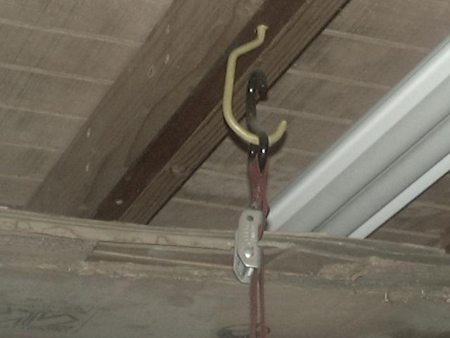
I installed 4 hooks (like you hang bicycles from) in the rafters in my
garage and attached some motorcycle tie-down straps (the
cam-lock kind, not the ratcheting kind) to the hooks and used
the crossbars from my roof rack to support the shell
- Slide open the side windows, one crossmember goes from window to window
- The second cross member goes under the shell *behind* the factory roll bar
- Lift an end of the shell up with your back and slide the crossmember under the gap
- Repeat one end then the other until you have sufficient clearance to drive out from under the shell
- This makes it a one-person removal and/or install process
-
And why not use ratchet straps?
- The typical ratchet strap only has a small spool and will only allow you to take up a short section of strap under tension. And yes you can slide the ratchet mechaism anywhere along the strap, but that is tedious to do and you really can't do that with a load on the strap. The cam-lock type straps are easy to adjust, you just squeeze the cam-lock, pull the slack out of the strap then release the cam-lock and the strat will take up the load. Ratchet straps work well for strapping down cargo where you need to pull the strat tight with a small motion. BGUt with lifting the top up a few feet, you just can't crank those kind of straps up high enough to do the job.
-
I put all the trim pieces and screws back on the shell after lifting it
off the truck so I know where they are when its time to re-install the
shell
- The trim pieces are very brittle, especially the long sections under the windows.
- Both mine broke and I repaired them by gluing pieces of plastic across the cracks on the inside of the trim
- Be sure that the tailgate is locked otherwise the "Rear Door" light will be on all the time
Note:
- The shell weighs in at around 200 lbs.
- The outside dimensions are 76.5" long, 59.5" wide.
Installation:
-
Place the shell on the vehicle
- I installed all the bolts in the bed rail to line everything up
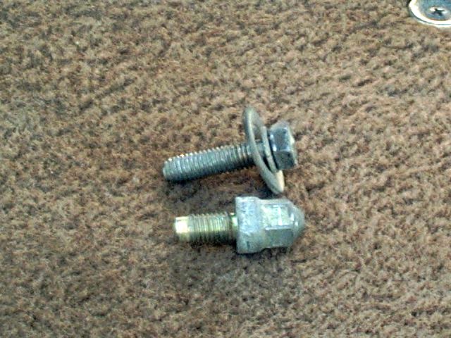
- Tighten bolts "B" M8-1.25x15mm (see diagram below)
- Tighten bolts "C" M8-1.25x35mm
-
Tighten bolts "D" M8-1.25x35mm
- The idea is to compress the seal along the bed rails
- Loosen bolts "C" M8-1.25x35mm
-
Tighten bolts "E" M8-1.25x35mm
- Now, you are compressing the seals to the cab roof
- Tighten all other bolts except "A" M8-1.25x35mm
- Tighten bolts "A"
- Uncover the hole and connect the wire and washer hose for the washer/wiper
-
Install the trim pieces and install the screws
- The plastic may be brittle
-
Tighten the bolts securely with a torque wrench:
- 102-149 in.lb. (8.5-12 ft.lb.)
Shell Storage:
So, you have the top off, now what do you do with it?
 |
 |
| A: Shell Hanger Detail | B: Shell Removal |
Here's how I remove and store my cover top (i.e. shell) in the garage.I can do this process all by myself, so no need to try and round up a neighbor or friend to come by to help.I use 4 cargp straps, not the ratchet type - those only have a limited take up length, but use the toggle-clamp style as shown in image A above. They are attached to 4 bicycle hooks screwed in the rafters of my garage. All these items came from the local hardware store.
The hooks are spaced wide enough to clear the sides of the top and far enough apart to line up with the front and rear windows. Then, I use some old aluminum roof rack bars, to which I fasten screw eyes to the ends (again parts from the local hardware store_. They are just wider than the top is, a pair of 2x4s would work, too. I slide the front window back and slide the bar though the opening. Then, I lift the top up with my shoulders and pull the straps tight on each side. This is one reason why I chose to use the open front windows for the forward support bar as there is no way (for me alone) to slide a support bar under the shell in front until it is lifted. And it is generally not possible to lift the rear of the shell first since the roof part will be pushed into the back of the cab, so this is why the front end must be lifted first (and also lowered last). And the final advantage of supporting the front of the shell with a bar through the windows is that when I have the shell lifted with my back/shoulders, it is easy to reach out the open window and take up the slack in the cargo strap.
Then in back, I lift the top up and slide the bar under the rear corner. I can reach out of the open rear window ro snug up the straps, or I can hop out and kift a corner and snug up that strap as needed. Then, its a matter of alternately lifting the ends of the cover top up and snugging up the straps until the top is against the rafters and then I simply drive out of the garage (I have to air down to 3 psi to get my 4Runner under the garage door!). To install is the reverse, back in, lower the and align the cover top, remove the bars and install the bolts. Simple, one person install and removal, no danger of dropping the top, either.
[Return to the top of this page]
![]()
Electrical:
Fuses:
Driver's side fuse panel:
| Rating | Circuit | Rating | Circuit | Rating | Circuit |
| 15A | Rear Defogger | 15A | Cigarette Lighter | 10A | Stop Lamps |
| 15A | Tail Lights | 15A | Windshield Wiper | 7.5A | Dome Light |
| 15A | EFI Circuit | 15A | Engine | 7.5A | Ignition |
Engine Fuse Box:
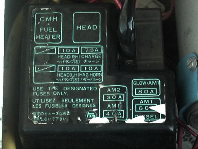 |
| Designation | Rating | Function |
| AM1 | 40 amp | Fusible Link / Gas Engine |
| - AM1 | 60 amp | Fusible Link / Diesel Engine |
| AM2 | 30 amp | Fusible Link / Gas Engine |
| - AM2 | 80 amp | Fusible Link / Diesel Engine |
| Head | 30 amp | Headlight Relay |
| Head(RH) | 10 amp | Right Hand Headlight Fuse |
| Head(LH) | 10 amp | Left Hand Headlight Fuse |
| Charge | 7.5 amps | Alternator Charge Fuse |
| Haz-Horn | 10 amps | Hazard Light / Horn Fuse - also Turn Signals |
| Fuel Heater | ? | Fuel Heater / Diesel Engine |
Senders:
| Sender | Low (ohms) | High (ohms) | Sender Thread |
| Fuel Tank | 110 = Empty | 3 = Full | n/a |
| Oil Pressure | = | = | 1/8"x28 BSP |
| Coolant Temp. | 24 = Hot/239F | 147 = 140F/Cold | . |
| Cold Start Injector Time Switch |
STA-STJ=20-40 below 30°C |
STA-STJ=40-60 above 40°C |
STA-Gnd 20-80 |
| Injector Resistor | 2 - 3 ohms each No10 or No20 to B+ |
. | n/a |
Factory Service Manual Wiring Color Codes:
| Code | Color |
| B | Black |
| G | Green |
| L | Light blue |
| O | Orange |
| R | Red |
| W | White |
| BR | BRown |
| GR | GRey |
| LG | Light Green |
| P | Pink |
| V | Violet |
| Y | Yellow |
Other Electrical Links:
[Return to the top of this page]
![]()
EFI:
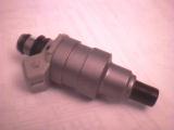
Recently, I opened up the intake side of my engine to inspect and clean the intake. This was prompted by a peek inside the throttle body, that revealed a thick layer of black goo. Upon removing the air plenum, I noticed a liquid in the bottom of two of the intake runners. A strong smell of gasoline suggested its source, the injectors must be leaking. After removing the fuel rail, the injectors just pop out of the intake manifold. They were a bit dirty, some solvent seemed to remove the surface grime, but I suspected, after 220,000 miles of use, they may be dirty inside. So, into a box and off to R.C. Engineering they went for the standard clean, calibrate and balance service. Three days later they arrived on my doorstep looking brand new with the following calibration report:
| Injector | cc/min | Pattern | cc/min | Pattern |
| 1 | 178.4 | Dripping | 184.1 | Excellent |
| 2 | 171.5 | Fair | 182.9 | Excellent |
| 3 | 177.9 | Good | 183.5 | Excellent |
| 4 | 179.0 | Good | 184.0 | Excellent |
All 4 injectors tested out at 3 ohms on my meter. Prior to service, the system balance was +/- 4.4%, afterwards 0.7% and total fuel flow increased from 67.31 to 69.95 lbs/hr, about a 4% increase, hopefully that will translate into some additional power at the wheels. All in all, a well spent $100.
Here's some related 22RE information:
[Return to the top of this page]
![]()
Wheels/Tires:
- Stock wheels:
-
15x6 steel
- 3-3/8" back side spacing (on '85 and earlier wheels)
- 4-3/4" back side spacing on '86 and later wheels, 15x6 steel or 15x7 alloy
- Here's a good backspace to offset calculator
- Center bore diameter: 4-3/8" (111mm) ID
- To fit over front hubs which are approx. 4-1/4" (or 106.1mm) OD
- And of course this implies a lug-centric wheel since the center bore is larger than the hub
- Beginning with the 3rd generation 4Runner and Tacoma models, wheels were changed to hub-centric
- 6 on 5.5" bolt pattern
- M12x1.50 thread pitch studs
- 3-3/8" back side spacing (on '85 and earlier wheels)
- Side-by-side comparison of the 33x9.50 BFG MudTerrain and 33x10.50 AllTerrain/KO tire
- A detailed summary of tire and wheel information
![]()
 ===>>
===>> 
Visitor # since 10.OCT.2001
[Last updated: 22.May.2025 ]