Brighter Headlights and more...
![]()
Contents:
- Headlight Combo Switch Repair
- H4 Headlight Conversion
-
Upgraded Headlight Wiring Harness
- Installation
- Try before you buy
- Types of headlight harnesses
- Technical Information
- On-line Ordering
- Brighter Headlight Bulbs
- Brighter Backup Lights
![]()
Headlight Combo Switch Repair:
My high beams started acting up, there seemed to be a slight (and very dark) delay as I switched them on. Sometimes it would take a few seconds before they clicked on. Then, they didn't turn on. I figured it might be the headlight relay (located in the engine bay fuse box on my '85 4Runner), so I got one of those, changed it out and no difference. Then I did a bit more diagnostic work and found the high beams would work in "flash" mode, just not by themselves. According to the Factory Service Manual, this indicates a problem in the "combo" switch. Note that the Combo switch is that lever behind the steering wheel with the knob you rotate to turn on the running lights and headlights as well as push back and forth to go from low to high beams and pulll back to use Flash mode (low and high beams both on). It is THE thing that controls the headlights on a Toyota. Rotating the switch on the end turns on the headlight relay to supply power to the headlights. Then to turn on the low or high beams, the combo switch supplies a ground connection to the headlights to complete the circuit and let the current flow through the headlight bulb filament and make light.
I decided I should at least have a look at this before springing for a special order (and probably high priced) replacement part. Pulled off the steering wheel and the trim around the steering column.
-
It may not be required to remove the steering wheel.
- It gives more working room and that is how I did this repair.
- I really don't feel like redoing the whole repair to try it with the wheel in place, after all if it ain't broke, don't fix it!
-
How to remove the wheel?
-
Pull the center cover:
- Usually some screws on the back and under sides.
- Loosen the retaining nut, screw it out the the end of the threads, but DO NOT remove all the way.
-
Then sitting in the driver's seat, grasp the wheel on each side and
give it a good tug.
- It should pop free.
- That nut you left on the end of the shaft will prevent it from flying back to hit you in the face.
- If pulling won't free it, try rocking the wheel side to side to loosen it on the splines.
- If the wheel won't remove by hand, get a steering wheel puller, available at most auto parts stores.
-
Pull the center cover:
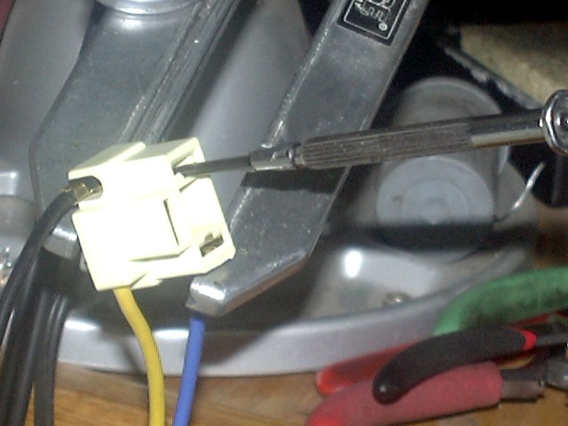
I removed the combo switch assembly with 4 screws, then found the 4 screws that held in the headlight switch. I found a lot of grease smeared all over the switch and this was probably the source of the problem. I think the grease was off the horn contact. I cleaned up most of it, but found the contact was still not good. The trusty Factory Service Manual had a schematic of the switch and is is very complex. There is one set of contacts that do energize the headlight relay, which in turn supplies power to the headlights. However, the switch itself actually switches the grounds to the headlights and has to pass the full current of two filaments through it. I think I will redesign this at a later date to have two separate relays, one for each high and low beam to eliminate the power loss of this complex wiring scheme, see below for how to do this...
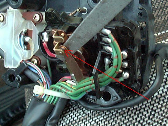
Anyway, I noticed that these contacts were a bit pitted from the high current they have to carry. I carefully filed each pair of contacts until I had nice shiny metal on each one. The red arrow in the photo above points to one of the switch contacts where the file is being used to clean up the contacts. So which contacts do you need to file? Simple answer is the ones that are pitted and/or dirty. A simple visual examination of each pair of contact will usually reveal their condition. The contacts should be flat and smooth, if not hit them with a thin file. And which contacts do what? Operate the combo switch and see which ones close and open in the various positions. The contacts that close when the lever is pushed forward are the ones that turn on the high beams.
I put it all back together, flipped the switch and there was light!
- Cost:
- Nada, zip, zilch!
- Rating:
-

- Note:
- This repair is only required if you are experiencing problems with either high or low beams not turning on and it is not a bulb or fuse problem. It is not a required step for upgrading headlights or the wiring harness. I only mention it here because it relates to the headlights. And actually, it was this very problem that prompted me to go through and upgrade the headlights and wiring so that this sort of problem would not recur.
And for later model ('90-'95 4Runner and '89-'95 pickup) vehicles, this thread has a good description of the headlight combo switch with photos.
[back to the top]
![]()
H4 Conversion:
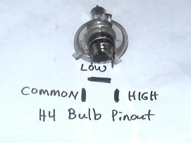
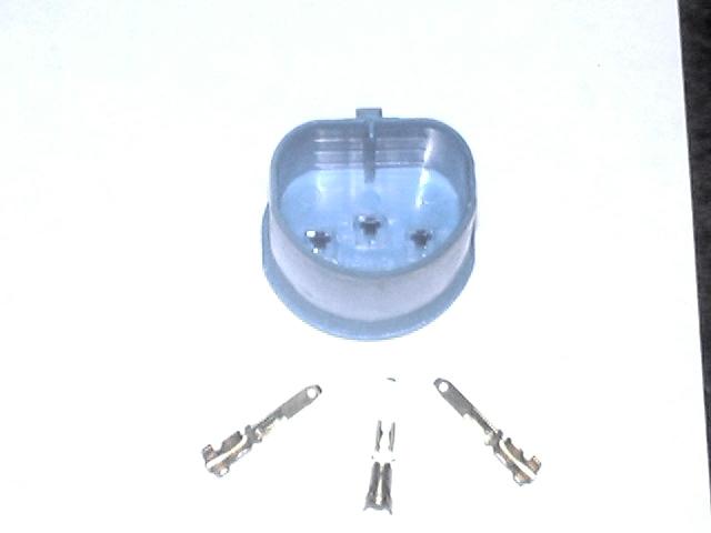
Years ago, I had replaced the old sealed beams (type 6054) with the Hella Vision Plus H4 halogen headlights (standard 6"x8" size). FYI, an H4 bulb has 2 filaments, one for low and one for high beam. It has 3 wires arranged in a "U" shape, 2 vertical, one horizontal. Newer vehicles use the 900x type connectors, which are shown in the picture below, they are usually rounded in shape and often are sealed. Probably a much better design than the H4, but I wanted to keep things stock.
- Note:
-
The Hella Vision Plus headlights I
installed use the exact same connections as stock, bolt into the exact
same mounting hardware as stock and they are DOT (street) legal in the
US. They have a very sharp horizontal beam cutoff on low beam and have
the upturned "eyebrow" in the light pattern on the right side
just like the E-code (euro) headlights. I've used them for nearly 20
years in various vehicles, and am happy with their performance. I
ordered the headlamp units from JC Whitney.
although there are many other sources for them.
- You'll want a 200mm rectangular lamp to replace a 6054 type sealed beam unit.
Since the bulb in the H4 headlight is separate from the housing, it is easier and less expensive to repair or upgrade. Instead of having to buy a whole new housing if a bulb burns out, you just buy a new bulb. Also, much easier to carry a spare bulb or two than to carry a bulky sealed beam lamp. Also, you have a wide variety of bulbs to choose from, with different power and light output ratings as well as a wide variety of housings from DOT legal to E-code (European spec) lights. And since all the parts are interchangeable, you are not stuck with the bulb that came with the housing.
- And a very important note:
- When installing or replacing halogen headlight bulbs, DO NOT TOUCH the glass part of the bulb envelope with your bare hands, fingers or any skin. Why? Because the oil on your skin will stick to the glass and when the lamp heats up, that oil residue will turn black and concentrate the heat of the bulb at the dark area, causing the glass envelope to fail. If you do happen to touch the glass, clean it off thoroughly with some isopropyl alcohol and a lint free cloth. Best option is to only handle the bulb with some clean gloves or with the bulb wrapped in a clean cloth.
![]()
Upgraded Headlight Wiring Harness:
So after dealing with repairing the faulty headlight combo switch (above) I didn't want to mess with that anymore. Also, after seeing the skimpy stock wiring and convoluted path that the headlight current takes, I decided it was time to upgrade the system wiring. So armed with the knowledge that Toyota headlights operated on a switch ground system, and that I use H4 style headlights in my '85 4Runner, I found a nice looking and well designed wiring harness kit to fit my needs, it supports 2 - H4 style headlights (one on each side) and works off of the switched ground system that Toyota uses:
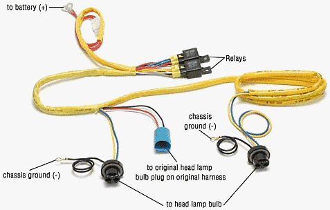
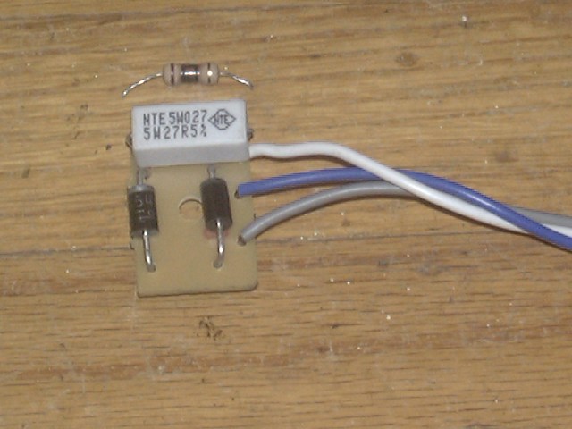
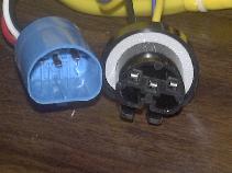
Pictured above is a 9004-style, switched power harness, but its very similar to the H4 harness I used. The blue connector looks like the back of a headlight bulb and you simply connect one of the existing headlight connectors to it. Also, not pictured in the above (switched-power) harness is a small black box used in the switched-ground Toyota system, which contains two diodes and a small resistor, which is used to direct a small amount of current back to the high beam indicator light on the dash. The harness is designed to accommodate horizontal headlight separations of approx. 6 ft.
[back to the top]Installation:
So on to the installation which consists of a few simple steps:
 |
| A: Headlight Wiring Harness Connection Note: The H4 style connector (3-wire) |
1. The connection shown in photo A supplies the control power to the two relays in the new harness. Just plug one of the stock (faded yellow) headlight connectors (female H4) into the (bright yellow) mating connector (male H4) on the new harness. It can only go in one way and there is only one male H4 connector, so it is hard to get this step wrong! Since this connector is close to the relays, which in turn have to be close to the power source. its best to use the headlight connector nearest where you intend to tap into power. Since I tapped into power at the engine fuse block, I used the passenger side light, your installation may be different.
Installation of the 9004 harness is similar to the H4 pictured. Match up the male and female 9004 connectors in a manner similar to the H4 connectors shown in the pictures.
 |
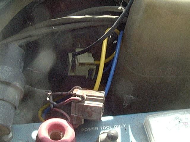 |
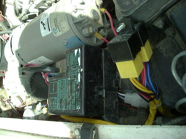
| B: New Relays and Fuse Block Connection |
C: Stock H4 Connector (unused) New H4 Connector Installed |
2. Then, connect the power leads, via a fuse (I used a single 30A fuse in my auxiliary fuse block, but two separate 20A fuses would also work well) to power (picture B - if no fuse block handy, you can run a fused wire off the battery or off the engine fuse box as needed). Or if you wish, the harness has fusible links built into the power leads and you could screw those right to the battery or alternator. However, a replaceable fuse or circuit breaker would be a more reliable connection (i.e. easier to repair if the fuse "blows"). A final option for a power connection, while not the most ideal, would be to connect the power leads to the stock headlight connector "common" terminal. This would be the terminal that goes to 12V when the lights are turned on. This circuit is fed by the stock headlight relay and fuse.
3. Then attach the two ground connections to the frame or body near by the headlights. I found a couple of body bolts that were a good ground points.
4. Finally, plug the two new connectors into the headlights (C) and you are done.
Note for Daytime Running Lights:
Daytime running light setups can be implemented in a variety of ways. There are two basic designs, one is a full voltage DRL and one is a reduced voltage (power) DRL. In a full voltage setup, typically the low beam headlight is simply turned on whenever the vehicle is running. In a reduced voltage setup, the headlights are also turned on when the vehicle is running, but at a reduced power level. This reduced power level is used to reduce glare to oncoming drivers and also to reduce the power load of the lights on the vehicle's electrical system. There are a couple of ways to reduce the power to the headlights in DRL mode. The simplest way is with a large power resistor in series with the light bulbs to limit the voltage and current flowing through them. When running, a typical 55 watt headlight bulb has about 3 ohms of resistance. With 2 bulbs in parallel (left and right side) you have a load of about 1.5 ohms in the light bulbs and a current of 12/1.5 or 8 amps flowing through them. So by simply inserting a separate 1.5 ohm resistor in series with those two bulbs, you now have a total of 3 ohms in the headlight circuit and a total of 12/3 or 4 amps of current flowing. This is the simplest way to reduce the power to the headlights in DRL operation. Then to get full headlight brightness, you simply add a power relay set up to bypass that power resistor with a pair of contacts. When bypassed you now just have the original full power current in the headlights. This resistor may be in the power or ground side of the headlights, it's location will vary with vehicle make and model.
A variation of the reduced power DRL is to use some sort of solid state power device to send reduced voltage to the lights, usually in the form of a pulse width modulated voltage, essentially like turning the light on and off very fast. If it is on 50% of the time and off 50% of the time, the effective brightness is reduced about in half. For this type of setup, it is probably best not to try and integrate a headlight relay kit, since relays are mechanical devices are typically can't operate when a rapidly switching voltage. Some folks have had luck with adding a capacitor in parallel with the relay coil to filter the rapidly changing voltage to make a smoother signal to use to turn the relay on.
As each make and model DRL system is different, you'll need to refer to a good wiring diagram for the vehicle in question to help determine how best to hook up the harness either to retain DRL operation or to bypass it as you see fit. Below are some typical DRL setups described and how one might go about integrating the new headlight wiring harness into various systems:
- For systems installed with Daytime Running Lights (DRLs), you'll likely be using a switched power harness (or switched ground harness modified for switched power operation). The way the typical late model Toyota (3rd gen 4Runner and Tacoma) DRL setup works is that there is a high power dimming resistor in the ground path of the headlights. In DRL mode, the dimming resistor limits the current through the headlights and gives a low power daytime light. When night falls and you need full light output, there is a relay that bypasses the dimming resistor in the ground path. So, if installing a relay harness and you wish DRL mode to still operate, you want to tie the new headlight connector ground (black) wires to the old headlight connector ground/common pins instead of to a body ground. This way, the headlight current will be limited in DRL mode, just like stock. However, if you wish to disable DRL operation, connect the new ground wires to a body ground point and take the appropriate measures to disable the DRL relay/module (procedure varies by vehicle).
- On the earlier model DRL systems (i.e early '90's Canadian vehicles) there is a DRL relay box that controls the DRL functions. To disable the DRLs, you can cut the black w/ orange stripe wire in the DRL relay box, if desired. The headlights work in a switched power mode and will work with or without the DRL relay functioning.
- Other vehicle makes or models may also have a DRL setup with the dimming resistor located on the power side of either the stock low or high beams. In this case, you will need to determine which beam the resistor is attached to. Then, if you want to retain the dim DRL operation, connect the power feed to the appropriate relay to that dimming resistor. So for example if the daytime running lights are the high beams in a dimmed mode, locate the high beam relay (that is the one with the two blue wires coming off it's 87 contacts) and connect the heavy red wire (with the fusible link and ring teminal attached) to that dimming resistor. This way when the DRLs are on, the high beam relay will be getting a reduced voltage and sending that on to the high beams via the new wiring harness. Then when the actual high beams are turned on, that relay will be bypassed by the vehicle's electronics and the high beam relay will then be getting full 12 volt power for a bright high beam. If the dimmed DRL is the low beam, use the above setup except substitute the low beam relay and it's power feed wire for the high beam relay. Likewise, if the dimming resistor is in the ground side of the headlights, you'll want to conenect the wiring harness ground wires (the black wires off the two new headlight connectors) to the dimming resistor instead of directly to ground, as described in the first Toyota case above.
So how well does the system work? In my opinion, it works great! The overall quality is very nice, the relays are socketed for easy replacement if needed. I like the fact that I can revert to stock just by swapping back to the old headlight connectors. This is handy if a relay dies on the trail, or I want to move the harness to a new vehicle. All the wires are run in protective looms, and everything is straight point-to-point connections, no splices or other mid-wire breaks.
Troubleshooting the Installation:
While I had no problems with the installation, there are a couple of possible issues you might run into. Summarized below are some common installation problems and some easy fixes:
-
No headlights on either side
- Likely there is a connection missing, either the male input connector is not plugged into the old harness (or that old connector wiring is bad) or the heavy power leads are not getting power.
-
Headlights work on one side but not the other
- Likely the ground (black) wire at the new headlight connector is not making proper contact with body sheet metal. Check the connection and if necessary, scrape a little paint off where the wire connects to the body.
-
No low beams on either side
- Likely a switched ground harness was installed on a switched power system, easy to convert the harness to switched power operation, or the low beam relay is not plugged in properly or is defective (see relay fix below).
-
No high beams on either side
-
High (or low) beam relay is not plugged in properly or is defective,
try swapping relays and see if that changes the situation. If so, a replacement relay may be ordered below.
- One other possibility is that water may have gotten into the relay case. This can happen if the relays(s) are installed with the wiring upward. If wet, you can pull the relay out for a day or so, place in the sun, connector pins up and allow it to dry out.
- Relays do not last forever, they have moving parts and make/break high electrical currents, so the contacts inside can and will wear out over a period of time. They are socketed for easy replacement for exactly this reason.
-
High (or low) beam relay is not plugged in properly or is defective,
try swapping relays and see if that changes the situation. If so, a replacement relay may be ordered below.
-
Low beams worked but then stopper working
- Check the resistor in the "black box", you may need to replace it with a higher power unit.
-
High beams come on with low beams (or low beams come on with high
beams):
- Most likely cause of this is that there is a problem in the headlight combo (dimmer) switch. Metal deposits on the switch contacts can result in a slight electrical connection even with the switch contacts open. While this connection may not have been enough to turn on the original headlights (to be visible), a relay will turn on with about 1% of the current that the headlight needs.
- To check this, use a volt meter to probe the 3 contacts in the unused factory headlight connector. You'll want to put one meter probe into the COMMON terminal of that connector (the one that reads 12 volts constant regardless of low or high beam mode. Then measure the bvoltage to the low and high beam terminals in low and high beam mode. Normal operation would be to see a 0-12 volt swing on low beam terminal when switching between higha nd low beam mode. Likewise the high beam terminal should do the same switching between low and high beam mode. But if you see other than 0 volts across say the low-common terminals with the high beams on or the high-common pins with the low beams on, then inspect the contacts in the headlight commbo switch for metall pitting/deposts...
-
If any of the above conditions apply, but the fixes above do not
correct the problem, it is likely that a wiring connection may have
been pulled or worked loose during (or after) installation.
- Check the wires where they enter the headlight connectors and the relay sockets. If you find a loose wire, you can try re-crimping it or better yet, use a soldering iron and solder the wire to the connector.
- You might have a female connector pin that does not make firm contact with, for example, the headlight bulb contacts. This is common as there is a wide variation in thickness of the tabs on the bulbs. If you find a "loose fit", simply pop the female connector pins out (one at a time) and slightly squeeze the sides of the connector pin with a needle nose plier until you get a good solid fit on the back of the bulb. Once tight, re-install the pin in the connector shell and repeat for the other pins, if needed.
- All the connectors have pins that can be easily removed with a small screwdriver to facilitate working on them.
- Application of dielectric (or bulb) grease on the connections is also a good idea, especially in wet or salty environments. The dielectric grease helps seal the metal-metal contact in the connectors and prevents oxidation and corrosion.
For a quick test of how effective the harness is, I used a volt meter across the headlight bulb to measure the actual voltage drop at the filaments (see image below). With the stock harness, I measured 10.6v and with the new harness, I got 12.6v. May not seem like a huge difference, but light output is proportional to approx. the cube (3.4 power) of the voltage, so (12.6/10.6)^3.4 is about 80% more light, for the same bulb no less. Pretty good for an under $40 harness and a few minutes of installation time. The wiring harness also provides internal diode protection for the stock headlight switch as well as proper loading such that the high beam indicator functions properly.
Try before you buy:
 |
| Measuring Headlight Voltage |
Your results may vary so you should really consider testing the voltage, as shown above, on your own headlights. This way you can see ahead of time what sort of "room for improvement" you have. It is important to do this test under load and compare the voltage across the headlight connector vs. the battery voltage. If you are seeing your headlight voltage is within about 0.5 volts of the battery, you are already "doing pretty darn good". Not a lot of room to improve and you are probably getting 95% of the light out of your headlights that is possible and you probably would not even notice a 5% increase if you were even able to get it. So, you would probably be better off not "upgrading" something that is already working optimally (or as they say "if it ain't broke, don't fix it"). Note that human eyes are not terribly sensitive to small increases in light output. For example, it is probably hard to detect a 20% light increase. Also, the increased light output you will see is often in the form of a more uniform light pattern (that is the dimmer areas are now closer in brightness to the brighter spots) rather than the bright areas being brighter. This results in a more useable light pattern (i.e. more light on the road) for driving, which after all is the whole point of the headlights. Also, if you decide you want to upgrade the headlight wiring, you will also know if you have a switched ground or switched power setup.
As it turns out, light output is approximately proprotional to the 4th power of the voltage across the filaments in the bulb. If the higher math is not your thing, have a look at the graph below. It shows light output for a typical halogen lamp on the vertical scale vs. lamp voltage across the horizontal scale. Compare the light output at your measured voltage to that you would see at your battery voltage. To do that, draw a line up at your measure voltage to where it intersects the red line on the graph. Then from that point, draw a horizontal line across to the light output (Lumens) scale and estimate the value. Repeat for the battery voltage and compare the two light outputs.
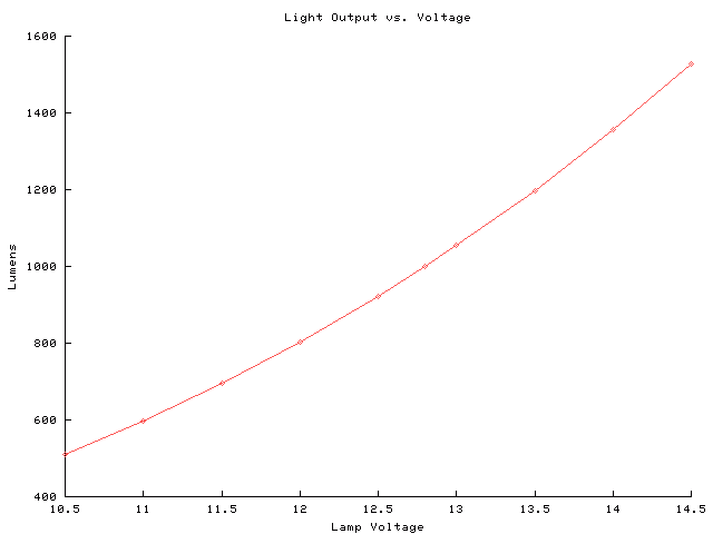 |
| Plot of Light Output vs. Lamp Voltage for a typical halogen headlight lamp |
Notes:
- The above voltages were re-measured with a fully charged battery and engine running and the system voltage to be 13.6v. and the lamp voltage to be around 13.2v with a pair of 100W high beams on.
- The light increase was also measured in another installation to have increased by approx. 80% with a light meter.
- Checking the voltage at the bulb connections is a good way to diagnose problems as well. Just pull the H4 connector part way off the bulb so that you can get a volt meter probe onto the contacts. The center contact is common to both filaments, the other two are high and low beam. Measure several voltages, one is across the filament that is on (that's what I measured above). Then if that voltage is significantly lower than the voltage across the battery, measure from common to the battery positive terminal and from the lit filament connector to a good ground point. If you are getting more than a few 10ths of a volt drop between power and the light or between the light and ground, look into the wiring and connections in those areas.
- The H4 harness will also work just fine with sealed beam headlights, either halogen or conventional style.
One thing to consider with halogen bulbs is that they last longer when run as hot as possible. The halogen gas inside the lamp combines with the (tungsten) metal ions that "boil" off the filament during operation and forms a tungsten-halide compound. This tungsten-halide circulates inside the bulb and when it hits the hot filament, it decomposes and redeposits the tungsten on the filament and releases the halogen back in gaseous form. This helps to keep the the light output more constant over time (since the tungsten does not deposit on the inside of the glass envelope) and by replenishing the tungsten on the filament, it does not burn out as fast. This chemical reaction takes place at temperatures in the 500°F-750°F range and when the bulb operates at the proper temperature, it can last many times longer than a normal incandescent bulb. However, when a halogen bulb runs too cool, this mechanism doesn't work as well so the bulb burns out faster and give less light. In fact, since halogen lamps and filaments tend to be smaller than normal incandescent bulbs, they can burn out much faster. This is sort of the opposite for normal incandescent light bulbs, they generally last longer at lower voltages. So, for maximum lifetime out of your fancy halogen headlight bulbs, you want to run the lamps as close to their full rated voltage as possible.
On the other hand, all the wiring harness is doing is supplying more of the system voltage that the bulb was designed for to the bulb. You will not get any more voltage than the vehicle's charging system is capable of delivering even if you used huge cables or even super conducting wires. So in no way will the harness lead to a light burning out from too much voltage. That is if your charging system puts out say 13.8 volts DC at the alternator, there is no way to get more than that 13.8 volts to the light bulb with any combination of (passive) wires and relays, all you can hope to do is to lose as little as possible of that 13.8 volts between the source (the alternator) and the load (the light bulb).
[back to the top]Which type of wiring harness do you need?
 |
 |
 |
Common       High
        Low
|
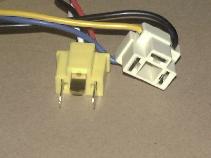
| A: H4-style Connectors | B: 9004-style Connectors |
-
You need to pick a harness that has the right number and kind of
headlight connectors that match your vehicle.
-
Harnesses for Toyota and other makes of vehicles with dual H4 and dual
9004 type headlights are available:
-
Dual headlights refers to 2 headlights, one on each side of the
vehicle, typically the 2nd pair of headlights are high beam only.
-
This is in contrast to quad (i.e. 4) headlights, arranged in a pair (or
2) per side of the vehicle. For a quad headlight harness, you have
several options:
- One is to keep the original headlight connectors for the high beams and let the original system drive them. Relieved of the added load of the primary headlights, the stock wiring should work fine with the lesser load.
- Or, use 2 dual harnesses, one for the main lights and one for the 2nd pair.
- Or the other is to splice in a pair of connectors to power the high beams off the existing harness.
-
This is in contrast to quad (i.e. 4) headlights, arranged in a pair (or
2) per side of the vehicle. For a quad headlight harness, you have
several options:
-
The H4 connector is square shaped (see photo A above) with three
contacts arranged like "|_|" and was used on Toyotas up until
the early '90s
- This includes standard sealed beam headlights, such as the 6054 sealed beams.
- H4 is also sometimes called HB2 or 9003.
-
The 9004 connector is oval shaped (see photo B above) with the three
contacts arranged like "-_-" and was used on some Toyotas
(such as the 4Runner) from the mid '90s onward.
-
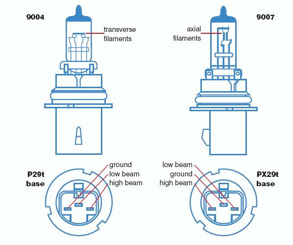
Also fits the 9007 style headlight connectors, although the low beam
and common pins need to be swapped for proper operation:
- That is on the 9004 pinout is Common-Low-High and on 9007 it is Low-Common-High
- Pins in the connectors are easily extracted and relocated with a small tool to depress the retaining clip inside the housing.
-
Also fits the 9007 style headlight connectors, although the low beam
and common pins need to be swapped for proper operation:
-
Notes:
-
Pictured above and male and female types of connectors (H4 and 9004).
In both versions, the connector to the right of the picture shows what
connects the wiring to the back of the headlight. In the left of both
pictures is the opposite gender connector that mates the new relay
harness to the existing headlight wiring. This makes for a true
"plug-n-play" installation:
- Unplug the old connectors from the headlight, plug the new connectors to the headlights and the mating connector to one of the old headlight connectors, then hook up power and ground and you are done!
- Bulb/connector pinouts above are typical but bulbs can vary, often the High and Low beam pins may be swapped with different brands.
-
Pictured above and male and female types of connectors (H4 and 9004).
In both versions, the connector to the right of the picture shows what
connects the wiring to the back of the headlight. In the left of both
pictures is the opposite gender connector that mates the new relay
harness to the existing headlight wiring. This makes for a true
"plug-n-play" installation:
-
Dual headlights refers to 2 headlights, one on each side of the
vehicle, typically the 2nd pair of headlights are high beam only.
-
Harnesses for Toyota and other makes of vehicles with dual H4 and dual
9004 type headlights are available:
-
Then you need to determine if you have switched-power or
switched-ground style headlights.
-
Most Toyotas and many Asian import vehicles often use switched ground
wiring for the headlights:
- One exception is vehicles with factory daytime running lights (DRL), they may be switched power...
- The 2005 and later model year Tacoma pickups use a switch power headlight wiring system
-
If you have a wiring diagram for the vehicle, look for the headlight
wiring, if the high and low beams connect to a switch that runs to
ground, then you have switched-ground, otherwise its likely
switched-power.
- See a typical switched-ground wiring diagram below...
- A switched power wiring harness is available here...
-
Or use a test light or volt meter to determine how the headlight socket
is wired.
- On a switched-ground system, you will find the common pin in the headlight connector will have constant 12V power supplied to it and then one of the high- or low-beam terminals will go to ground when it is on.
- Switched power systems will usually have the common terminal tied directly to ground and one or the other terminals will go to 12V when the light is turned on.
-
For a simple test, take a volt meter and plug the BLACK (-) probe into
the COMMON terminal, then plug the RED (+) probe into the LOW beam
terminal. With the meter on a 20 volt DC range, measure the voltage.
- If the meter reads -12V or so, then you have switched ground, i.e. the reading is negative, since you have the "-" probe on the battery side and the "+" probe on the ground side.
- If the meter reads +12V or so, then you have a switched power system.
- Under high beam operation, you can sometimes get confusing voltage readings, since often voltage is fed back from the high beam side to the low beam side to illuminate the high beam indicator light on the dash.
- If you have daytime running lights (DRL) you probably have a switched power system. The DRL relay and limiting resistor will be in the ground side of the headlight circuit. If you want to retain DRL function (with the dimmed daytime low beams), you'll need to connect the new harness common/ground connection to the old harness common/ground connection. Otherwise, connect the new harness common connection to ground and you'll either have full brightness DRLs or if you have disabled that feature, then you'll have normal lights.
-
Some High Intensity Discharge (HID) headlight conversion kits use an H4
connector. They use the High/Low beam part of the existing headlight
circuit to mechanically move the HID lamp inside the housing to change
it's focus. This is another use for this relay harness, it can drive
the High/Low beam part of the HID lamp as well as providing the
back-fed power to operate the high beam indicator on the dash.
- This is an important factor in areas that do regular vehicle inspections, as proper operation of the high beam indicator is one item commonly checked.
-
Be sure to use the right kind of harness, running a switched-power
harness on a switched-ground headlight can damage the headlight switch
with extended use.
- The switched ground harness has additional circuitry to isolate the low and high beam relays and most importantly to provide the power to illuminate the high beam indicator light, as is done with the stock wiring.
- This is needed because in stock form, the high beam indicator actually is powered by current "leaking" though the low beam filament (when it is turned off that is). When a relay is installed in place of the actual light bulb, the 15-20 mA of current that the relay coil uses is not sufficient to illuminate the high beam indicator, so it'll appear to be "burned out".
- The switched ground harness feeds current back from the high beam relay, via a diode and resistor, to power the high beam indicator.
- It is also possible to "convert" the switched ground harness to work in a switched power mode, see below for details...
-
Most Toyotas and many Asian import vehicles often use switched ground
wiring for the headlights:
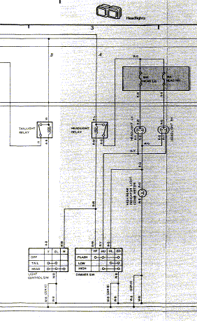
DESCRIPTION: POWER FUSE HEADLIGHTS HIGH BEAM INDICATOR HEADLIGHT/DIMMER SWITCH GROUND |
|
| Example of '85 Toyota Headlights w/ Switched-Ground Wiring |
As can be seen, the SWITCH is on the GROUND side of the headlights, thus SWITCHED-GROUND! |
Bottom line:
-
If in doubt of which type of harness to use, get the switched-ground
version.
- It is easy to convert it to switch power operation if needed.
- Also, the switched-ground harness, if used in a switched power system, will simply not turn the low beams on, while a switched-power harness in a switched ground system may cause excessive currents to flow in the harness.
Implications of switched ground / HID conversions:
One place where a switched ground wiring scheme comes into play is with aomething like an HID conversion. Why is this? Well, if you look at the way the switched ground system works, you have a common 12 volt supply to the headlights. Then the actual headlight bulbs are not hard-wired to ground, they are in a sense floating with respect to ground. Then the headlight combo/dimmer switch grounds one or the other bulb filament to complete the circuit, allowing the current to flow and lighting the bulb.
The problem with many aftermarket components is that they are designed with a built-in ground connection via the case of the device. That is there is usually some sort of metal box for the device, like an HID lamp ballast, and when that metal case is screwed into the vehicle's sheet metal, that forms the ground connection. Now the trouble comes when you try to tie a floating ground system (like the headlights) to a hard-wired ground system like an HID conversion kit, you may get interactions between the hard ground in the HID kit and the floating ground in the headlights. This can cause problems like flickering lights, blown fuses, or worse. Similar problems happen with devices like radios and guages connected into the dimming dash light circuit, which is also a floating ground setup.
So why are devices built like this? Likely becuase almost all vehicles built in the US and Europe are built with switched power and hard wired grounds, so most aftermarket vendors build devices that "plug-n-play" nicely with those type of vehicles. It is also easier to make systems where the chassis of the device is metal and grounded and then any internal ground connection can simply be made to that chassis, and that also helps shield out electrical noise from things like the ignition.
So what can be done to remedy this issue? The easiest way to handle it is to convert the headlights to a swithed power setup. That is easiest handled with a relay kit on the headlights, like described on this very web page. Since relays could care less what direction the current flows in their coils and also since common relays are electrically insulated internally, they can handle the switched ground to switched power transition and leave everything downstream from them in a conventional switched power / hard-wired ground configuration.
And why did Toyota (and many of the other Asian automobile manufacturer's) choose to use switched ground wiring in their vehicles? Well, first off, much of the vehicle is wired in a switched power mode, so it is not a 100% thing by any means. But I think there are a few possible advantages of using switched ground wiring. For one, since all the devices so wired are essentially insulated from ground, they are somewhat protected from short circuits. For example if the power connection were to touch the case of the device, nothing would happen since it is not grounded. Also, since the wires and switches controlling the turning on and off functions are on the ground side of the circuit, nothing damaging will happen if they somehow get accidentally grounded. That is since they normally connect to ground, if one of those wires gets accidentally grounded, the light attached to that circuit will come on like normal, but there will be no blown fuses or burned up wiring or switch.
But if switched ground wiring were such a superoir system, why not wore the whole vehicle that way? On my '85 Toyota 4Runner, I find that the headlights, horn, dimmable dash back lights and some of the power window controls are wired in switched ground mode. Pretty much everything else is wired in the more conventional switched power mode. Easy way to tell is to look at the factory wiring diagram for the circuit you are interested in and see where the control for that circuit is in relation to the device is. Remember that power runs along the top of the diagram and ground is at the bottom. If you see power-switch-device-ground, then you have the switch on the power side (i.e. switched power). But if you see power-device-switch-ground, you have a switched ground circuit.
In the end, switched power or switched ground really makes no difference in terms of function, lights still light up, motors still turn on, etc. It is nowhere near as significant of a problem as like a 6 volt system or a system where the positive connection is ground. But, you can still get into problems adding devices, that are typically built for switched power, to a switched ground system. One simple example is the common accessory switch from the auto parts store. They usually include a built in light that comes on automatically when the switch is turned on. These switches typically have 3 wires, POWER, GROUND and LOAD. They are set up to connect POWER to LOAD and then internally the light is connected to GROUND and gets POWER from the switch to turn it on. But you think you want that switch light to be dimmable like the rest of the dash lights, so you connect POWER to the dimming light power. Guess what? That is a switched ground, or rather floating ground circuit, the dimming lights all tie together at the dimmer rheostat which is connected to ground. So you hook up the switch and the light in it is now shorting out the rheostat and that will mess up the dash lights. So you can either get POWER from a switched power circuit (losing the dimming function) or you might try swapping POWER and GROUND connections on the switch, assuming it has a regular bulb and not an LED, this may work. Doing this will of course send a ground signal to your relay or whatever the switch is operating, so it will also be switched ground. Now all would be cool if the switch mfg. were to simply provide 4 wire terminals, 2 for the switch and 2 for the light, then you could wire that however you wanted to. But that 4th terminal costs money and when they are cranking out millions of switches per year, that adds up. So, if you have a vehicle with switched ground wiring, just be aware of these sorts of issues when adding aftermarket devices (that are typically built for switched power operation) to any switched ground circuits on your vehicle.
[back to the top]More Information:
Here is some technical information discussing the design of the switched ground headlight wiring harness and how it works:
 |
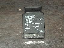
| Switched Ground Wiring Harness Schematic: - D1, D2 = 1N5404, 3 amp diode; Radio Shack p/n 276-1144 - R1 = 10 ohm, 1/2 - 1 watt resistor; Radio Shack p/n 271-151 or heavy duty 5 watt resistor - Relays: 30-amp Bosch-style 12V relay, 5-pin, DPST (or 2-Form-A) e.g. SongChuan #792-2AU-01 or Amperite #AR2-2A01-2D01-F -- Do not use a SPDT relay (form C contacts), they will not work in the high beam socket |
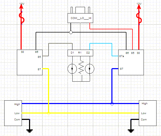
Above is the wiring schematic of the switched ground wiring harness.
- At the top-center is the input connector that mates to one of the existing headlight connectors to control the relays.
- At the top left and right are the low- an high-beam power feed lines with built-in fusible links.
- At the center left and right are the low- and high-beam relays, typical Bosch 30 amp headlight relays.
- At the bottom left and right and the new left and right headlight connectors.
-
In the center is the switched ground wiring circuit, that does several
functions:
- D1 allows the low beam relay to be turned on my the factory low beam headlight signal
- D2 and R1 is used to feed power back to the high beam indicator light on the dash to turn it on.
- Note that high beam relay contacts 87 and 87a turn on and off at the same time (i.e. DPST or 2-Form-A design).
-
So 87a connects to terminal 30 and send power back to light the high
beam indicator (via D2 and R1) when the high beam relay is on.
- Be careful when using a 5-pin SPDT relay where contact 87a switches opposite to contact 87, as the above circuit may need to be modified to work properly.
-
Wire colors may vary from harness to harness. Also, the diagram is
drawn for clarity and does not reflect the physical layout.
-
For example there are 2 YELLOW wires connected to the LOW BEAM relay
that run to the LOW BEAM headlight connectors on the bottom.
- Wire size is typically 12 ga. for the power feed wires and 14 ga. for the headlight wires. As there is one pair of wires to bulb (one for low and one for high beam), coupled with the short run of wire, results in a resistance of approx. 0.016 ohms and a voltage drop of about 0.125 volts over the longest side wire with a 100 watt bulb.
- Likewise, the diode/resistor box wires may be laid our physically different than shown in the diagram, it was drawn as shown to be easier to see and understand rather than to show the physical parts layout.
-
For example there are 2 YELLOW wires connected to the LOW BEAM relay
that run to the LOW BEAM headlight connectors on the bottom.
- Here is a good link describing how the 30/40 amp headlight relay works, what the various pins do, etc.:
[back to the top]
How to convert a switched power harness to switched ground operation:
It is possible to run a switched power headlight harness in a vehicle that uses switched ground wiring. How is that? Simple. relays do not care which way the current flows through their coils, in fact a relay can even work on alternating (AC) current. But the one thing that may not work is the high beam indicator on the dash, depending on how it is wired. If that light depends on current flowing through the headlights, adding relays will reduce that current enough to make the dash light not work. But before converting the harness, you may actually want to temporarily plug the switched power harness into your headlights to both verify that high and low beams work normally (they should) and if your high beam indicator lights or not. At least this way you'll know that everything with the harness and your existing headlight system is working before you decide to convert the harness, if needed, to switched ground operation.
So it is possible to make the high beam indicator work as noted below.
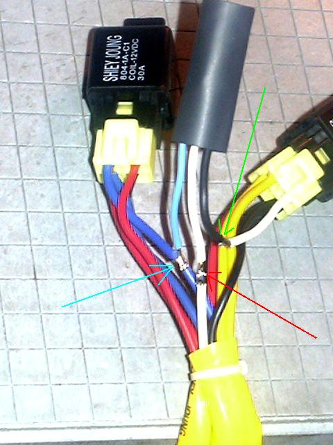
As can be seen in the above diagram, there are only 3 wires that connect the switched ground "black box" to the wiring harness. Note that if the "black box" has a connector attached, you can simply cut the 3 wires at the connector, or alternately, you can use female spade lug terminals crimped onto the cut harness wires to attach the switched ground box.
 |
| Switched Power to Switched Ground Conversion |
Pictured above is the 3 wiring connections required for the Switched Ground conversion:
- One connection is to the high beam power connection, so either of the two blue wires works for that. Note that in the above diagram, there is only one blue wire whown, but physically there are two blue wires coming from the high beam relay, one to each headlight. Also, there is no "87a" terminal on the swtched power harness, since that terminal is electrically connected to the "87" terminal (on the switched ground harness) that the blue wires are connected to, just pick either of the blue wires. You want to tap into that wire with the blue wire (light blue arrow in the above photo) from the "black box", making a tee connection. This wire is what supplies power to light the high beam indicator on the dash.
- The other two connections are actually to the same harness wire. You simply cut the white (low beam) wire from the input connnector (male H4) and hook the connector end to the "black box" white wire (red arrow in the above photo). This wire both sends power from the original headlight circuit to the low beam relay as well and sends power back to the high beam indicator on the dash.
- Finally, connect the "black box" gray or black wire to the harness/relay end of the cut white wire to complete that circuit (green arrow in the above photo). This wire sends power to the low beam relay.
Be sure to tape or apply heat skrink over the wire connections to insulate and waterproof them. Now test the harness and you should find that high and low beams work as normal and verify that the high beam indicator on the dash is now working.
Basically what you are doing is getting the high beam signal (via the blue wire) that gets sent back for the high beam indicator on the dash via the white wire. Then that white wire also picks up the low bam signal (from the headlight switch) and sends it to the low beam relay, via the gray wire.
[back to the top]How to convert a switched ground harness for switched power operation:
-
It is also possible to "convert" the switched ground harness
to work in a switched power mode.
-
To do this, simply tie the gray and white wires together inside the
"black box" or you can unsolder and remove the diode
connected to the blue wire and reverse the diode connected to the gray
wire inside the box, or even simpler, take a short length of wire and
add a male spade lug to each end and insert into the connector where
the "black box" used to attach (see picture "B"
below)
- NOTE: Wire colors may vary from harness to harness, so what you are trying to do with the above connection is to hook the wire that comes off the old headlight LOW BEAM pin (normally a WHITE wire) to the low beam relay's "85" coil pin (normally a GRAY wire). If your wires are a different color, disregard the color descriptions and go by the "what it connects to" description. You want to get power from the LOW BEAM connector to the RELAY COIL.
- Either method lets current flow the "other way" through the low beam relay to let it operate normally.
- The high beam relay is wired to work in either polarity.
- Click on either image below to bring up a full size version...
-
To do this, simply tie the gray and white wires together inside the
"black box" or you can unsolder and remove the diode
connected to the blue wire and reverse the diode connected to the gray
wire inside the box, or even simpler, take a short length of wire and
add a male spade lug to each end and insert into the connector where
the "black box" used to attach (see picture "B"
below)
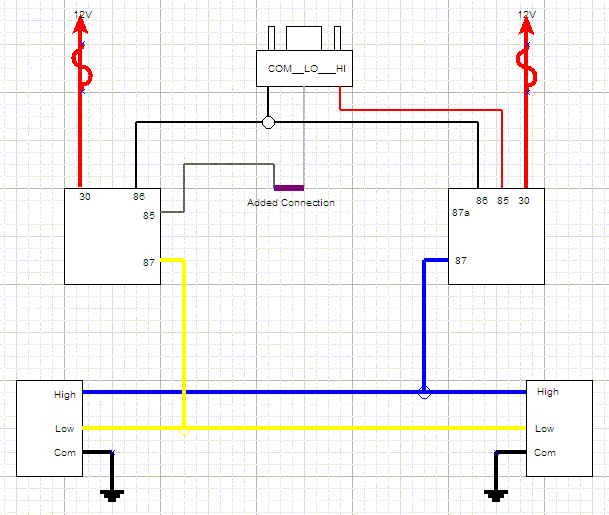 |
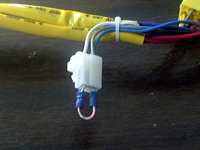 |
| A: How to Convert Switched Ground Harness to Switch Power Operation |
B: This can be done with a simple plug-in jumper |
[back to the top]
Swapping High and Low Beam Connections:
Unfortunately, the wiring of high and low beams on headlights is not always the same, at least on the H4 type bulbs. While most commonly they follow the pinout shown here, they can sometimes be wired such that the high and low bear connectors are swapped. So instead of Common-Low-High, you have Common-High-Low. You can test this case out with a volt meter or test light on your headlight connector to see which pins have voltage with high and low beams on.
If you find yours are wired backwards, it is a simple matter to swap the pins in the connectors. For the male-H4 input connector, insert a small, flat-blade screwdriver into the front of the connector to gently depress the little clip that hold the connector pin in place, and pull it out the back of the connector. Do this for the White and Red wires then re-insert them in the opposite location than they came out of. Likewise, on the female H4 output connectors, do the same with the Blue and Yellow wires. There are a few different situations where this may need to be done. First if your whole vehicle is wired with the swapped high and low beams, then swap both the input and output connectors on the harness. Second would be if your vehicle is wired normally, but you purchase and install a new set of headlights and find that they work "backwards". That is the high beam lights up with the headlight switch is in low beam mode and the low beams light up when the highs should be on. In this case, only swap the 2 female H4 output connectors (the ones that plug into the headlights).
Also, if you find the connectors fit loosely on your headlight bulbs, you can pop the male connectors out of the shell and gently tighten them with a pair of needle nosed pliers:
[back to the top]Fine Tuning Tips:
As you can see from the above sections. this wiring harness is very flexible in terms of reconfiguration. Here are some additional notes if you want to fine tune the harness to do other things:
-
The resistor (R1) in the "black box" basically controls the
brightness of the high beam indicator on the dash. Normally, you see
the "resistance" of the low beam filament in series with the
dash light.
- The supplied 10 ohm resistor is a bit higher resistance than the filament, so the dash light is a tiny bit dimmer than stock, I found the dash light was too bright in stock form.
- Swapping the R1 resistor for something like a 27 ohm resistor (Red-Violet-Black color code) cuts the dash light brightness down even more.
- At around 50 ohms, the dash light is very dim, hardly visible in daylight, or you can remove R1 altogether, although see the note below about using "flash" mode.
- So, if you feel the need to dim your high beam indicator light, you now have the information to do so.
- Also, some vehicle's seem to draw more current through this circuit than others. If you experience overheating of the 10 ohm resistor, this may be the case. An upgraded resistor that is able to withstand even a continuous short circuit is available for replacing the stock resistor.
-
One interesting thing is observed in "flash" mode, that is
pulling back on the dimmer switch. This normally pulls on the high
beams momentarily and may turn on the low beams as well. The high beam
indicator will not, however, be illuminated, due to the way the
indicator light is wired.
- With the switched ground harness in place, only the high beams will be on in "flash" mode and the high beam indicator will be illuminated. So, this is a bit different operation than stock, still useable.
-
If you "really" want the flash mode to hit both high and low
beams and you want the high beam indicator to work properly, what you
need to do is convert the harness to switched power operation (as noted
above) and then run the "87a" wire from the high beam relay
back to the dash and have that wire supply power to the high beam
indicator directly, disconnecting the high beam indicator from the
return line from the low beam light.
- This is really the way that the high beam indicator should have been wired from the factory, but doing so would have involved running an additional wire between the dash and headlights, plus the connectors and whatnot to make that happen. So, to save a few pennies/yen/whatever, the existing wiring was used.
-
Note, you should not hold the "flash" mode on for a long
time.
- Doing so can cause the R1 resistor to overheat, since you are essentially connecting it between 12V (from the high beam relay) and ground (from the headlight dimmer switch). Put 12 volts across 10 ohms and you have 1.2 amps flowing and about 14 watts of power dissipation. The resistor is rated at 1 watt (or less) so leaving the flash mode on for a significant period of time will burn up the resistor. If you want to use flash mode a lot, you might consider replacing R1 with a 20 watt / 10 ohm wire wound resistor. A resistor that size is about the size of the black box. Another option would be to replace R1 with a small 12 volt light bulb, like a 10 watt festoon bulb (like the dome light). This will handle the power dissipation.
-
Another interesting configuration option with flash mode is that some
folks have expressed an interest in having the low beams stay on with
the high beams for added light output.
- This is possible by simply inserting a SPDT switch between the D1 diode in the "black box" and and the low beam relay "85" terminal. The 3 poles of the switch are wired such that the center pole is wired to the relay's "85" (coil) terminal, then one of the other poles wires to the gray wire from D1 in the "black box" and the other pole is wired to ground.
- In the normal position, the switch will pass the normal low beam control signal to the low beam relay and it will work in normal fashion, on with low beam and off with high beams.
-
Bypassing that diode, with the switch in the alternate position, will
let the low beam relay stay on all the time (that the headlights are
turned on), regardless of the high or low beam setting.
- Since this switch is only handling the current of the relay coil (~160 mA) it does not need to be a high current switch.
- Alternately, for permanent conversion, simply disconnect the gray wire from the "black box" and connect it to ground.
- Doing these modifications may cause damage to the lamp housing from the extra heat generated and may or may not comply with local vehicle regulations, so proceed at your own risk. Likely would be of most use in off-road situations, anyway.
Heavy Duty Switched Ground Resistor:
For some vehicles, an upgraded resistor may be required if there is too much current draw in the existing headlight system. A 5 watt 47 ohm resistor is available for $5.00 that can be used to replace the existing resistor. Swapping the resistors involves unplugging the "black box". One screw holds the cover in place. Remove the small PC board and use a soldering iron to remove the 1 watt resistor (small component shown in the picture below). Then insert the new resistor leads and solder it in place. Replace the cover and plug the "black box" back in place in the harness. The upgraded resistor is capable of sustaining a continuous short circuit across the "black box", so makes the circuit self-protecting.
You can also find 5W resistors on Amazon if you prefer.
 |
| Heavy Duty Resistor shown installed on the "black
box" PC board resistor shipped separate, must be soldered in place |
This order button is only for US shipping. Contact us if you need this part shipped to another country or use the Amazon link above instead.
- How do I know if I need this resistor?
-
A simple voltage test across the resistor with either the low- or
high-beams on will tell you. If you see more than about 2.5 volts
across the resistor, in either low- or high-beam operation, then your
vehicle's wiring is pulling more current that the resistor can handle.
The upgraded resistor can take upwards of 12 volts across it
continuously. Typically less than 5% of vehicles seem to need the heavy
duty resistor.
- Another common sign that you need the HD resistor is if you lose your low beams. This can happen if the standard resistor is overloaded by your vehicle's high beam indicator wiring and it can change resistance and/or become an open circuit. If this happens, it is a simple matter to unsolder the old resistor (inside the "black box") and solder in the new resistor.
Spare Relays and Sockets:
The supplied relays in this harness are rated at 30 amps DC and there is one relay for the high beams and one relay for the low beams. This setup is conservatively rated to operate 100 watt bulbs. Assuming a 12.5 volt operating voltage, a pair of 100 watt bulbs pulls approx. 16 amps (2 * 100 / 12.5 = 16.0). So the relays are operating just about 1/2 their rated current to ensure a long operating lifetime.
That said, relays should be considered wear items. They have moving electrical contacts and those arc when making and breaking the high headlight current. This is why they are socketed for easy replacement. This is much better than the OEM setup with the factory headlight combo switch contacts wearing out over time. Those are expensive to replace and difficult to access.
Available below is a replacement 30 amp relay if you want to carry a spare or replace a burned out relay. Both relays are the 5-pin 2-Form-C Bosch style relays and feature 2 separate output contacts (87 and 87a). Also available is a 5-pin relay socket that can be used for building your own headlight harness, or adding additional relays to a harness (for example upgrading to a 4 headlight setup) or for swapping out relay sockets, for example the 4-pin relays used on the switch power harness, to the more common 5-pin Bosch-type relay:
 |
 |
| Standard Output (30 amp) relay - $5.00 + shipping | 5-pin Relay Socket - $5.00 + shipping |
These order buttons are only for US shipping. Contact us if you need this part shipped to another country or use this Amazon link instead.
[back to the top]Volts, amps, and watts for incandescent bulbs:
So how much current does a light bulb use? Actually that is a tricky question to answer, as "it depends". An incandescent bulb is really a variable resistance type of load. When the filament is cold, it has a low resistance. As it heats up, the resistance increases to the point a "steady state" is achieved, that is the current becomes a steady value. At that steady state value, you can use the basic power formula that watts = volts time amps to determine that watts/volts = amps. So for a 55 watt bulb with a nominal 13 volt supply (typical for a running vehicle w/ "12 volt" battery), you would see approx. 4.23 amps flowing through it. But at various voltages you'll see other values:
| Volts | Amps | Resistance | Watts |
| 1.0 | 1.34 | 0.76 | 1.34 |
| 2.0 | 1.75 | 1.14 | 3.50 |
| 3.0 | 2.15 | 1.39 | 6.45 |
| 4.0 | 2.48 | 1.61 | 9.92 |
| 5.0 | 2.82 | 1.77 | 14.10 |
| ... | ... | ... | ... |
| 13.0 | 4.23 | 3.07 | 55.00 |
The above data was measured by setting the voltage to various values then measuring the steady state current, then calculating the resistance(ohms) and power(watts). Now, it is unlikely that one would run a 12 volt bulb at 1 volt, but the value of the above data is in determining the resistance of the bulb at low temperatures and how that affects the "inrush" or initial current. Using the "cold" 1 volt resistance of 0.76 ohms and comparing that to the "hot" 13 volt resistance, you can easily see that the cold resistance is about 4 times smaller (3.07/0.76 = 4.04). That means that with the full system voltage applied across a "cold" bulb, you can see a startup current of about 4 times as large as the steady state "hot" current. So, at startup, that bulb that pulls 4.23 amps, will draw over 17 amps (13/0.76 = 17.1) for a brief time during the initial startup. That is why you want to leave a little "head room" with your relays. That is' use a relay with more current capacity than the lights need while running.
[back to the top]For more information, see:
- JC Whitney is good source of headlight housings and bulbs
- Rally Lights is another good source for headlight housings and bulbs
- Daniel Stern Lighting is another good source of automotive lighting information and products
[back to the top]
On-line Ordering:
-
The H4 and 9004 headlight wiring harnesses are currently out
of stock.
However, we are working on a new harness design and hope to be producing those soon. Updates will be posted to this web page when the new harnesses are available.
-
Domestic shipping is US$7.00, contact us for multiple unit, expedited
shipping options.
- Domestic via Priority Mail (2-3 days typical) w/ Delivery Confirmation number e-mailed upon shipping
- Orders via Paypal eChecks are subject to a 3-4 day delay for the eCheck to clear
-
International shipping is US$34.95 to most destinations, contact us for
multiple unit shipping options.
- International via Global Priority Mail (where available), 7 days typical delivery time
- Includes 2 relays and mounting hardware and general installation instructions
- You'll need to supply a power source connection (and optionally fuse(s)) to connect the harness to your vehicle.
- Select the type of harness based upon the type of headlight connector you have.
- Switched ground harnesses should work with many Asian imports, including Toyota, Nissan, Datsun, Mitsibishi, etc.
- A Heavy Duty (HD) switched ground harness is also available for $5.00 additional. It includes an upgraded current limiting resistor suitable for use on late model vehicles which can pull more back current through the high beam indicator light.
-
Domestic shipping is US$7.00, contact us for multiple unit, expedited
shipping options.
 |
 |
| Dual H4 Style Harness, Switched Power w/ Switched Ground black box, US Delivery |
Dual 9004 Harness, Switched Ground, US Delivery |
| . | . |
| Dual H4 Style Switched Power Harness, w/ Heavy Duty Switched Ground Box, US Delivery | Dual 9004 Harness, Heavy Duty Switched Ground, US Delivery |
| ================================================= | ================================================= |
| Dual H4 Style Harness, Switched Ground, Int'l Delivery - A telephone number is required for customs paperwork - add it to the "Note to Seller" field in the order form |
Dual 9004 Harness, Switched Ground, Int'l Delivery - A telephone number is required for customs paperwork, - add it to the "Note to Seller" field in the order form |
| . | . |
| Dual H4 Style HD Harness, Switched Ground, Int'l Delivery - A telephone number is required for customs paperwork - add it to the "Note to Seller" field in the order form |
Dual 9004 Harness, HD Switched Ground, Int'l Delivery - A telephone number is required for customs paperwork - add it to the "Note to Seller" field in the order form |
[back to the top]
Want to roll your own?
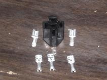
If you want to make your own relay wiring harness or convert from one type of headlights to another? No problem. Usually most of the items needed are available like wire, relays, replacement headlight connectors (female), but if you have trouble locating any of those items, we stock a small supply of Bosch-style headlight relay sockets, 30 and 40 amp headlight relays, and female H4 and 9004/9007 headlight sockets.
The hard to find item is the male connector that mates the relay harness into the existing wiring. Now they are available in both an H4-male and 9004/7-male connector shell with pins that you can use to make your own harness or use to convert one type of headlight to another. For example, if you have a 9004/7-equipped vehicle and want to upgrade to H4 headlights, order the H4 harness and the 9004/7-male connector and then swap the H4-male connector on the relay harness for the 9004/7-male connector and you are set and have made no changes to the factory wiring. The relays will be controlled via the 9004/7 factory wiring and will send their output to the new H4 connectors on the harness to the new headlights. The 9004 and 9007 headlights share the same physical connector shell, but the high/low/common pins are swapped, so depending on how you wire up the connector shell will determine if it is a 9004 or 9007 type of connector, see below for the 9004 vs. 9007 bulb pinouts:
 |
| 9004 vs. 9007 Bulb/Connector Differences |
The male connectors cost US$12.00/ea. plus shipping:
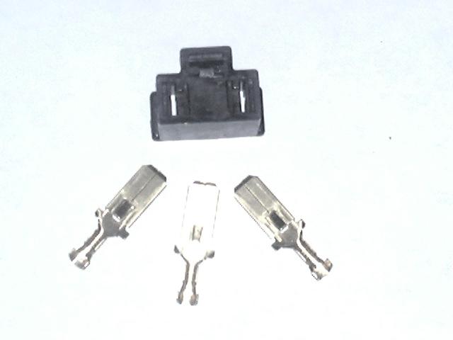 |
 |
| H4 Male Connector | 9004/7 Male Connector |
|
|
Also available are additional and/or replacement H4 and 9004/9007 female connector shells and pins. These are useful for adding additional connectors to a harness, for example to drive a second pair of high beam headlights (as in a quad headlight setup), or to replace a damaged connector in either a relay harness or in the factory harness, or even to make a conversion harness, as noted below. Female connectors cost $8.00/ea. plus shipping:
| . | . |
| H4 Female Connector | 9004/7 Female Connector |
|
|
You can also order headlight relays and sockets here...
[back to the top]Need a conversion harness?
In some cases, you may find you need to change the type of headlights in your vehicle. For example, you may have a 9004 headlight currently, but want to upgrade to a more widely available H4 setup. To do so, you need to change out the headlight connectors. Instead of swapping out both headlight connectors, another option is to use a relay wiring harness kit, that is also built to convert the type of connector as well. For example, if the harness were set up with a male 9004 connector to mate with the original 9004 connector in the vehicle, and if it had female H4 connectors for the new headlights, you could install the harness with no changes to the factory wiring, a true plug-n-play installation. If you want an H4 or 9004 harness pre-configured with an opposite (9004, 9007 or H4) male connector, that can also be done for a cost of $25.00 plus the cost of the relay harness and connectors. More information available via e-mail.
[back to the top]Brighter Headlight Bulbs:
So, now I had this nice new wiring harness installed and it gave a decent boost in light output, but there is always room for more. I was happy with my 55W low beams. Plenty of light and with a lifted truck, I'm considerate of other drivers and don't want to blind them with too much light. But the 60W high beams, while decent, could use some more light output, so I found some 55-100W H4 halogen replacement bulbs p/n 07UV6039N (not the plasma/diamond/xenon/etc. non-white lamps). They just swap into the Hella H4 housings (mine are the DOT Vision Plus - maybe not the absolute best headlight out there (pretty darn good for a DOT lamp, there are undoubtedly better E-code lamps available) but they are paid for. Pop the bulbs in and on top of the 80% increase from the new harness, I get about 66% more from the increases wattage, so well over twice as much light. The bulbs cost about $20/ea. and added to $40 for the harness gives a good result for about $80 investment plus my original $70 H4 housing investment.
- So why not just add some extra driving lights?
-
I don't like a lot of lights on my truck. I run a set of Hella 550 fog
lights on the front bumper and the headlights. I don't like the look
and its more things to block air flow to the radiator and get damaged
on the trail (or stolen in the parking lot). I like my existing lights
to work and do double duty.
- For example, high beams work pretty good off-road for high speed night driving, except they leave a dark area just in front of the truck, so I've wired the fog lights such that I can turn them on independent of the headlights to fill under the high beams (but not any more, see below).
- So how do they work?
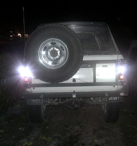
- One word, WOW! The big difference I find from before is the light coverage is more filled in. The brightest areas are about the same, but the surrounding areas or much more illuminated. Before, my high beams lit up down the road well, but left a huge dark void in front of the truck. I used to have to run with the fog lights on on winding roads to get enough light on the sides of the road to see the upcoming turns. Now, the high beams are sufficient. I like the combination of stock 55W low beams and the higher power 100W highs. With stock wattage low beams, I don't find I'm blinding oncoming drivers.
- So why didn't you use XYZ Super Duper headlights?
- My goal wasn't to make the absolute best lighting system money could buy. I wanted something that was adequate for my needs, reliable and affordable. I also didn't want to attract any more attention from law enforcement personnel than necessary :) Sure, using 10 ga. wire in the harness would have been better, using 80/130W bulbs would have been better, using different lamp housings would have been better. How much better and at how much extra cost in time and money? I also didn't want any cheesy blue light or those funky lights that change color, good old white light is all I want. I'm happy with what I ended up with, I realize there are other ways to do this, to each his own.
- IMPORTANT TIP:
- When replacing halogen bulbs, DO NOT TOUCH THE BULB WITH YOUR FINGERS. Oils on your skin will get on the bulb envelope and when it heats up, it will burn, leave a dark area and that can and will lead to overheating and ultimately cracking of the quartz envelope. This can happen in a very short period of time. If you do happen to touch the bulb, accidentally, wipe the glass clean with isopropyl alcohol before installing it.
Brighter Backup Lights:
Part-I:
I had read this article and thought it might be nice to try. I had tried higher wattage bulbs before in tail lights and found the results disappointing. The bulbs were expensive, didn't seem to last very long, burned out a reverse switch in my daily driver and if that wasn't enough, they were not very much brighter. The is just not a good enough reflector to put out a lot of light, so making the reflector better is probably a good idea.
 |
| Rear tail light housing/reflector |
So, while the above article is good, I wanted to show the whole lamp assembly. Above, you can see the factory reflector w/ 3 light bulbs on the top, the Red/Clear/Orange transparent lens and the separator, that just sits between the other two parts. 6 phillips head screws hold it all together, 2 hold the lens to the reflector and the other 4 attach the assembly to the body. All 6 screws must be removed. There is a gasket between the lens and reflector, mine is well attached, but be sure not to lose it.
Pull out the separator (mine was a dull gray or black color as I recall), clean it with alcohol and paint it. I used a Rustoleum Metallic Chrome (finish pictured above) and its retained its luster and gloss after many years of use. After drying, put the separator and lens back on the reflector and reinstall the assembly back in place. I found a decent increase in light output in reverse at night. For the cost (nearly 0) and time (under an hour total) it is a good improvement and only makes you wonder why the separator was not mirrored at the factory?
Part-II:
While there was some improvement in backup light output with the above work, it still seemed that the stock backup lights were pretty weak. It seems the light from the bulb is more or less scattered all over the place instead of being focused to the back like you would expect. To remedy this, I obtained a pair of 30-LED, white, 1156 type bulbs (from SuperBrightLEDS.com) to replace the stock incandescent bulbs. I opted for a narrow beam light output, taking advantage of the internal lens in the LEDs to focus the light independent of the reflector in the tail lamp. I had to grind a little bit to remove some plastic nubs in the stock reflector to fit the oversize bulbs, but the results are very nice:
 |
| 30 LED Backup Lights |
Part-III:
While the above mods work well around town, I would still like more light for off road use. I'm not big on having mega-lights on my truck, but there have been times a little more light while backing up on the trail would have been nice. I plan to install a pair of 50W clear halogen fog lights on my rear bumper/tire carrier once its done. They'll be up high enough to throw some good light in back and to the sides, but will be out of the way on the tire carrier (and I already have the lights, salvaged from my totaled daily driver a few years ago).
But, I already have enough lights and accessory switches and really don't want to add another one to fumble with in the dark. So to automate the lights, I'm planning to install a relay in the reverse light switch circuit, which will provide a contact closure when the transmission is in reverse. Then, I'll do the same with the 4WD switch in the transfer case. Then, using the two contacts in series, I'll run a 3rd relay to power the new reverse lights. This way they only light in reverse and in 4WD. I don't normally use 4WD around town, so this should help avoid blinding other drivers when I back out of a parking spot. I'll also add an override switch that will let me enable or disable the reverse light relay.
More on this project as it progresses.
[back to the top]

Visitor # since 28.AUG.2001
[Last updated: 24.November.2023]
![]()