Rock SliderZ Assembly
If you purchased the Rock SliderZ in kit form, the following instructions will guide you through the assembly process. For the parts cuttig list, simply cut the raw material as per the cutting guide. Even if you purchased pre-made ones, you can see how they were assembled. If you simply want to copy my design, you'll see how they are built. No special welding equipment or processes are required. Any welder with 100-120A capacity will work, arc, MIG or fluxcore is fine. I normally use 1/8" 7014 or 6013 rod at about 110 amps. Since this is a small enough part, try to orient the bars to facilitate flat or horizontal welding position as you put them together.
For the kit, you should have:
- 4"x4"x1/4" base plates
-
1.5"x1.5" (or 2"x2") rear legs
- Some models have 2 middle and 2 rear legs
-
1.5"x1.5" (or 2"x2") angled front legs
- Angled on some models
- 8 1.5"x1.5" outrigger legs
- 8 2.5"x2"x1/8" end caps
-
2 2"x2"x1/8" inner bars
- Included in the full kit
- W/ mini-kit, bars are cut approx. 2" shorter than the wheel well - wheel well distance
-
2 2"x2"x1/8" (or 3/16") wall outer bars
- Included in the full kit
- W/ mini-kit, bars are cut approx. 2" shorter than the inner bars
- 3/8"x1" self tapping bolts (if ordered)
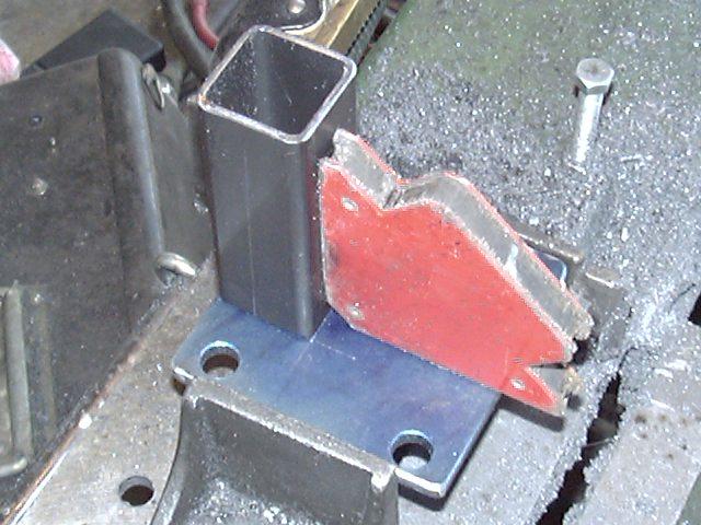
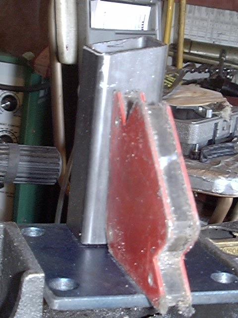
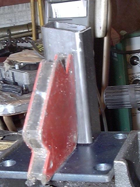
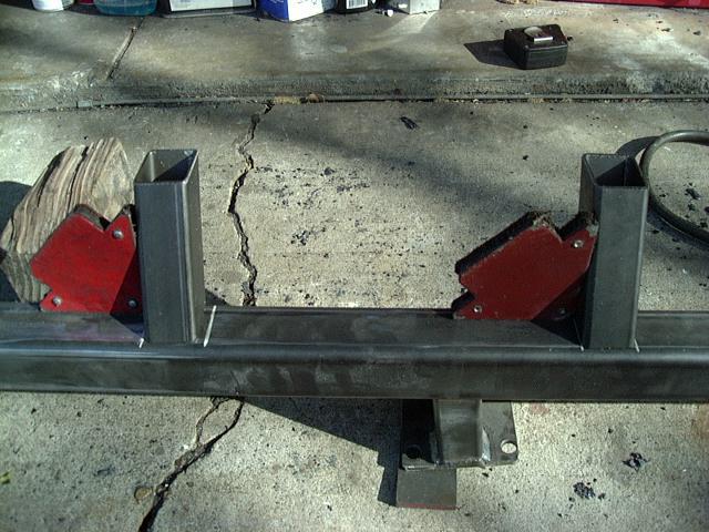
I fabricate the mounting brackets first. I use a right angle magnetic jig to hole the leg perpendicular to the base, centered side to side and flush with one edge. Note the orientation of the mounting holes. For the front legs, be sure to place the square end onto the base, the angled end will go against the inner bar. Also, be sure you make the two front brackets with angles in opposite directions. If in doubt, test fit the bracket on the frame and see if its correct before laying down the weld bead.

Once the legs are tack welded to the base, place a gusset in the center of the leg, then weld around all 4 side of the leg and the gusset to finish the bracket. Repeat for the other 3 brackets.
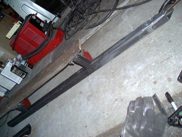
Next, locate the inner bar. It is the longer of the bars. The front bracket should be located 21-1/2" back from the front end of the bar, the rear 13-1/2" forward from the rear end of the bar. Make sure the beveled ends of the bars face down and I like to place the welded seam towards the inside. On the 0"-1" body lift versions, the bracket feet stick up from the inner bar, on the 2" and 3" lift versions, the feet stick down. You may want to tack weld the brackets on and then test fit them on the truck. Also, be sure you get the correct front bracket on each side. Be sure that the top of the bracket lines up with the top of the inner bar, I use a pair of magnet jigs to hold everything in alignment. In the picture you will notice I use a wooden jig to hold the brackets in place. The jig is not necessary, I use it to reduce my fabrication time and increase quality. Tack weld each bracket in 2-3 places before finishing the weld.
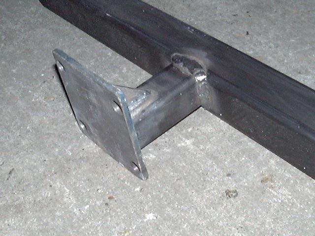
Weld each bracket to the inner bar on all 4 sides. Repeat for the opposite side, making sure to orient the forward bracket correctly.
If you are making a bar with kickouts front and/or rear, there are two options. One is a notched bar, the other is offset bevel cuts.
- For the notched bar, lay the bar on the ground, with the cut out notch facing down, over a scrap of wood. Stand on the middle part and press down the end to bend the tube until the notch closes. You can fine tune the bend by grinding out any high spots. Once bent, turn it over and weld up the cut. On the 3/16" wall tubing, you may want to grind a bit of a bevel in the cut to allow fuller penetration. Lay in a root pass, clean it up and then lay in a filler bead that stands out from the surfae a bit. It may take a few passes to fill it in all the way.
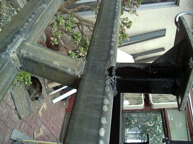
- For the offset bevel cuts, you need to match up the angles of the main part of the outer bar and the 12" long ends that will angle outward. A 1" kickout has approx. a 5° angle, a 2" kickout has about 10°. You want the two angles on the main bar and the end to match up to angle the end out away from the main tube. To line up the ends and get an equal kickout angle on all the ends, lay the outer bar with it's inside face dow, then add blocks of the desired kickout amount at the end of each kicked out end. Then apply a welding magnet to what will be the top and bottom face of the bar, across the joining seam of the two pieces of tubing to hold the kicked out end in line with the main tube. Then hit the outer face of the joint with a few light tack welds, then a few on the top and bottom face and finally tack the inside face. Once all side of the joint are tacked, run a bead around the joint. For strength, you can leave the weld bead, grinding off any rough or high spots if you want. Some folks like to grind the top of the seam smooth.

Next, place the outrigger section on the inner bar. Line up the rear outrigger with the rear mounting leg. Space the bars equally along the inner bar, approx. 12" on center. If you have the outer bar with kickouts, make sure not to set the forward outrigger beyond the bend. Make sure the outriggers angle upwards, and are approx. centered on the inner bar and perpendicular to it. Once again, magnetic angle jigs make this setup easier. Tack weld a few spots and once all 4 outriggers are tacked, place the outer bar on top. Center the outer bar on the outriggers and check the fit. You may find that one outrigger may stick up too far, due to it not sitting flush on the inner bar. If this happens, either remove and re-tack it in place or grind it down a bit to fit. Once the outer bar fits fairly well, tack weld it to the outriggers and then proceed to weld all the outriggers on all 4 sides to both the inner and outer bars.

Finally, the last welding step is to fit the end caps on the bars. A pair of magnets work well to hold the cap in place. Tack it then weld on all 4 sides. Before tacking on the final 2 end caps, tip the bars up and shake out any accumulated scale and slag from inside. Next, grind out any exposed weld for a better finish. I usually grind the end caps smooth and slightly round the corners and then may grind down the top surface of the kickout weld.
Here is a bar that has been cleaned then acid etched and coated with a zinc phosphate coating. After it is dry, a base coat of POR-15 is applied, followed by a second coat in 4 hours. After that fully cures, it is sanded out and a coat of POR-15 ChassisCoat is applied, allowed to dry then sanded out. A final top coat is then applied.

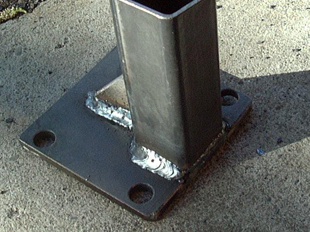
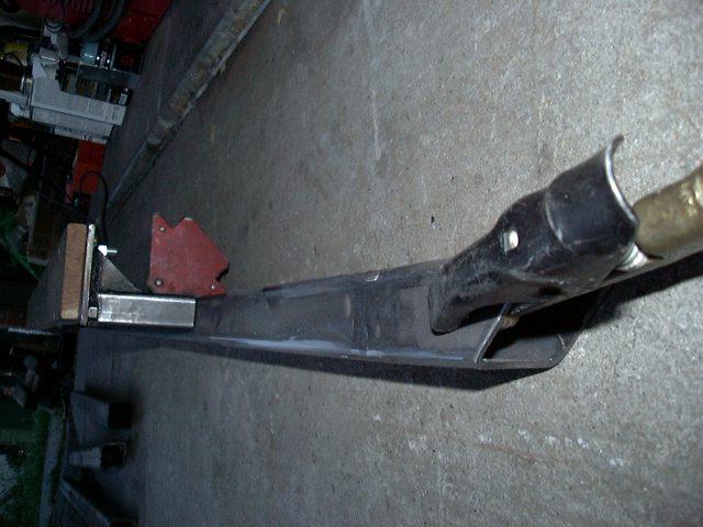
Here's a closeup of the mounting bracket and self-tapping bolts.
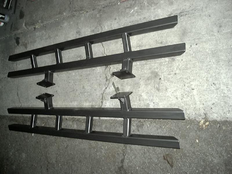
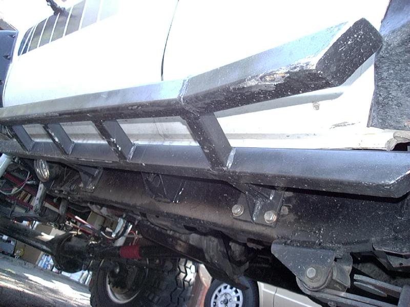
And here is the finished product. I recommend adding a non-abrasive non-slip tape on the top surface of the outer bar. I once used a gritty tape and found that it would scrape my legs getting in and out of the truck wearing short pants. I use a rubberized 3M grip tape, 1" wide, that seems to hold uup well and provides plenty of grip even when wet.
Rock SliderZ Assembly Instructions, v0.93
[Last updated: 23.March.2021]
Visitor # since 28.AUG.2001
Copyright © - 4Crawler Offroad 2001-2019 - All Rights Reserved The latest version of this document may be found at: https://www.4crawler.com/4x4/ForSale/Docs/NerfBarKit_HowTo.shtml