![]()
VW Diesel Glow Plugs
Visitor # since 19.SEP.2001
![]()
Contents:
[Return to Diesel Cheap Tricks page]Introduction
What would a diesel be without glow plugs? (beside harder than the dickens to start!)
Glow plugs are used to pre-heat the indirect injection chamber on some diesel engines for ease of starting. VW has two different glow plug systems, called slow and fast. Each system consists of a high current relay (with integrated starting logic) and glow plugs. It is important not to mix the fast and slow components.
The glow plug relay is the heart of the glow plug system. It gets input from a temperature sensor on the cylinder head which it uses to adjust the duration of the glow plug pre-heat cycle depending on the engine's temperature. Longer when cold, shorter (or not at all) when its warm (or hot). The sensor it located on the heater hose fitting on the end of the cylinder head. It should be a brass sensor with a single connector stud on the end, screwed into the body of the fitting. In fact, you should actually have two such sensors, the other one is used for either the coolant temperature gauge (or idiot light) on the dash. An obvious question arises, which is which and what happens if they are mixed up?
Well, it sort of depends. On some early VW diesels (maybe through 1984), the senders are different. If you have only an idiot light, you can tell its sensor easily by use of an ohm meter. The sensor will probably read open when cold and then close when hot (to turn on the idiot light). The glow plug sensor will register some resistance (between 100-200 ohms when cold). If you have a temperature gauge, its sensor will register a higher resistance at any given temperature than the glow plug sensor, probably 500-1000 ohms when cold. If you get the two mixed up, you'll find the glow plug relay may cycle on and off after starting before the coolant heats up. Since the other sensor registers higher resistance, the relay is thinking it is *really* cold. You may also get the little yellow glow plug light blinking on and off. (Both of these symptoms happened to me with switched sensors).
On later VW diesels (around 1985) the two sensors (assuming you have the temperature gauge) are identical and both measure about 1000 ohms. So if you have this type of vehicle, you can't mix up the sensors.
Finally, on some of the latest VW diesels, the glow plug temperature sender is now a simple on-off device. According to the Bentley '85-'92 Jetta Diesel manual, the glow plug sender should be closed below 50°C coolant temperature and open above that temperature.
So, what does this all mean? It means there are lots of combinations of temperature senders and probably glow plug relays to go with them. I've found some glow plug relays are very sensitive to the temperature sender input resistance. Others tolerate a wide range of resistances (they are probably a later design). Best bet is to find a relay design that works and stick with it. If you experience "weird" glow plug problems, this is just one more variable you'll need to address.
[return to the top]Troubleshooting:
Troubleshooting the glow plug system consits of testing the various system components in a logical order. The order to test the system in needs to take into account the ease of accessing parts. You need to make sure power can get to the glow plugs, then that the relay is capable of supplying that power when needed and finally that the plugs themselves are functional.
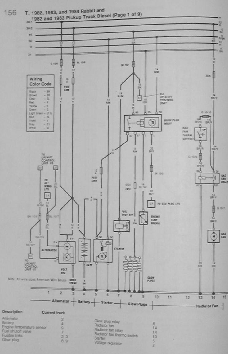
The above schematic diagram shows the electircal components and connections in the VW diesel glow plug system.
Here are some handy troubleshooting tips for testing the various aspects of the glow plug system:
- The wire from the glow plug temperature sender can be disconnected so that the system will operate regardless of engine temperature
- A test light connected to the glow plug bus bar is handy to observe if the plugs are receiving power
-
Inputs to the glow plug relay are easily tested in the relay socket,
the pins are identified on the schematic:
- 30: Should have battery voltage present at all times
- 50: Should have power when the starter is operating
- 85: Ground for the relay socket, pinds 30-85 should read battery voltage at all times
- 86: Should have voltage when the key in in the "pre-glow" position
- 87: Power output to the glow plugs themselves
- L: Sends power to the glow plug LED on the dash
- T: Receives the input from the temoperature sender on the cylinder head
Fusible Link:
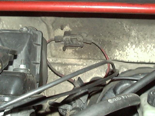
The first (and easiest) component to check if you suspect glow plug problems is the fusible link (see photo above), located above the heater control valve on the firewall on the A1 platforms. It may be under a black plastic cover (mine is missing:). On the A2 and later vehicles, the glow plug fusible link is typically under the dash, near the glow plug relay, under a clear plastic cover.
The link is a thin piece of metal that acts as a fuse for the system. It should have two heavy gauge wires running to it. In some vehicles, the fusible link is inside, under the dash. This would be the case if you follow the heavy gauge wire from the glow plug bus to the firewall and find that it goes through without terminating. In this case, find where the wire comes through under the dash and follow it towards the glow plug relay. There *should* be a fusible link somewhere between the relay and glow plug bus. This is a safety item, this circuit is easily capable of sourcing 50-100 AMPS, which could make bad things happen if it were to short out to ground.
Make sure the metal link is intact and that the nuts are tight. It can't hurt to remove the link and clean the contacts to ensure good current flow. If blown, a replacement is available from the dealer. Hint, if you have to buy a replacement, get a couple so you'll have a spare next time.
[return to the top]Temperature Sensor Testing:
The glow plug relay uses a coolant temperature sensor located on the heater outlet on the cylinder head. This is located just below the oil pressure sensor also attached to the head. Usually there are two sensors screwed into the heater outlet. One is for the coolant temperature gauge (or idiot light) on the dash (with a BL/Y wire), the other is for the glow plug relay (with a BL/W wire). The two sensors are different.
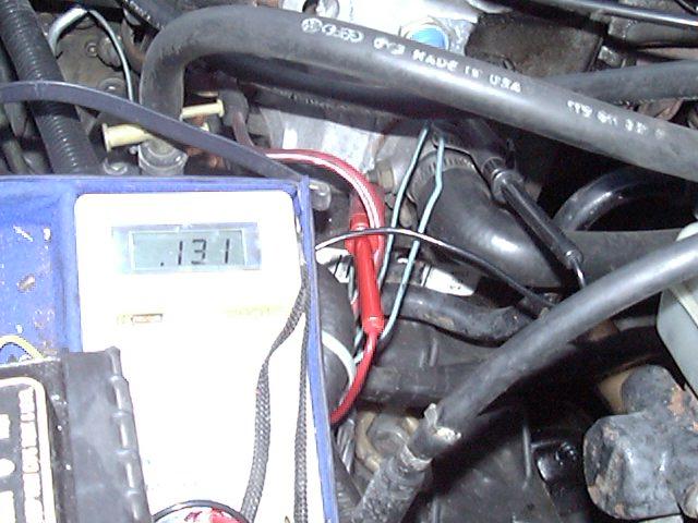
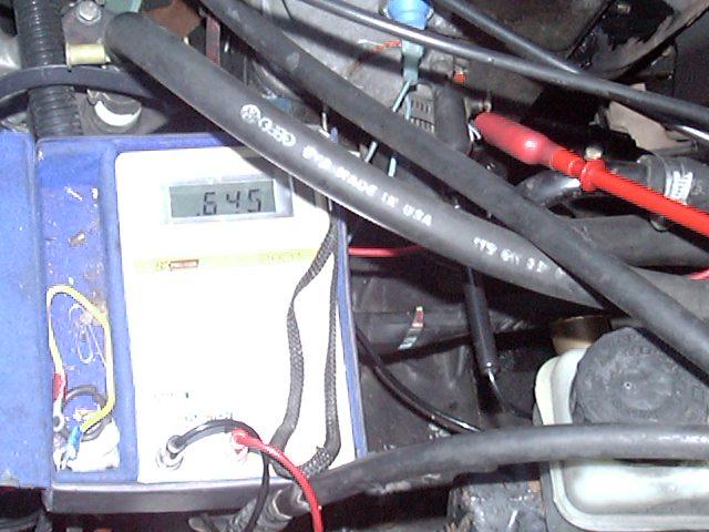
Pictured above left, you can see how to test the temperature gauge sender, the ohm meter is reading 131 ohms with slightly warm coolant. On the right is the glow plug sender test showing a nominal 645 ohm reading. Both readings vary with temperature (that's how temperature sensors work), I did another test at an outside air temperature of 60°F (15°C) and found the temperature sender read 1600 ohms, the glow plug sender read 1200 ohms. On some vehicles, the two senders are the same VW p/n (068-121-145D) others are different and some later models have a simpler open/closed sender for the glow plug relay, with continuity below 120°F (50°C) and open above that.
If the sensor reads much outside this range, it is probably bad and should be replaced. If the senders are different and the two wires are swapped, you'll have abnormally low temperature gauge readings and abnormally long glow plug cycles as best or the glow plug relay will just stay on continuously. If the resistance reading is nominal at the sender, check it under the dash at the glow plug relay socket. This signal is present at the connector labeled "T", read resistance from there to ground. If you get a different value than you read at the sensor, there is a problem in the wiring or the connector itself.
Another way to check that the temperature sender signal is reaching the relay is to disconnect the wire from the sender and cycle the glow plugs. If the relay stays on for a much longer period of time (than with the wire connected) its probably working fine, if not, you probably have an open circuit between the sender and the relay. The other test is to ground the wire from the temperature sender. The glow plugs should not come on with the pre-glow cycle. If either the LED or glow plugs come on with this test suspect either a faulty temperature sender wire connection or a bad relay.
[return to the top]Glow Plug Indicator Light
So you have the little yellow glow plug LED on the dash, why do you need another glow plug light? Actually, the LED on the dash has nothing to do with the glow plugs. Its just an output from one part of the glow plug relay, which takes the temperature sender input and produces a delay to let the glow plugs reach the proper operating temperature. The glow plugs themselves are powered by a relay which is operated by a different part of the relay circuit and they generally stay on for a time after the LED goes out. If the coolant temperature is warm enough, the glow plugs and LED won't be turned on at all in the "glow" position of the ignition switch. However, the glow plugs are always turned on whenever the starter is operating, regardless of temperature.
By running a wire off the glow plug bus bar to a light on the dash, it will be possible to observe when power is actually reaching the glow plugs directly. This indicator would be useful to diagnose a number of glow plug problems.
- A faulty glow plug relay may not provide power to the plugs leading to hard starting, for example corroded contacts in the relay. You would see the LED go on and off, hear the relay click on and off, but yet no power would reach the glow plugs.
- A faulty temperature sender could result in the relay running the plugs too short or too long for the conditions.
- The relay contacts can get welded shut, leaving the glow plugs running all the time, greatly reducing their lifetime.
- A flaky relay could result in spurious cycling of the glow plugs while the engine is running. This type of problem would be nearly impossible to diagnose without the indicator light.
Well, when it finally came time to install this secondary indicator light, I had a second problem to solve. I found one of my windshield washer nozzles was hopelessly clogged and would no longer spray. I tried a fine wire to clean it out, but no luck. Then I found out that the one nozzle I needed was NLA (no longer available). So looking around, I found some of those lighted (LED) washer nozzles for a reasonable price, around $10-15/ea. While those are popular in some circles to have lit up at night, I thought this would make the perfect glow plug indicator and would make installation/wiring a piece of cake. I simply crimped on a large ring teminal to each of the power wires for the nozzles and put one on each side of the glow plug fusible link and then tied the two ground wires together and screwed those to some bare sheet metal. Viola, two LEDs light up with the glow plugs. If only one lights up, this means the fusible link has blown and if none light up, the relay is bad.
During the day, can't really see the LEDs light up from the driver's seat, but you can hop out and see then for troubleshooting purposes. At night you can see the red glow easily. And to top it off, the washer nozzles work very well, they have two separate jets that you can aim separately for better spray coverage.
[return to the top]How do you test glow plugs?
I've found that when I have one bad plug, I may not notice any starting problem in warm weather and maybe just a little cold smoke. With 2 bad plugs its harder to start, especially when cold or at high elevation and you'll get rough idling and cold smoke until the engine warms up. 3 bad plugs and you'll be lucky to get going, and if you do you'll make a most impressive smoke screen!
In the vehicle, you have a few options.
- Use an accurate digital volt meter to measure the voltage drop from the plug to plug along the bus bar. You can usually detect a 1-2 mV (0.001-0.002V) drop due to the current flowing from plug to plug. If you see no drop between two plugs, then its likely there is no current flowing.
- Use an ohm-meter or test light to see if the plugs have continuity. Almost every glow plug will fail open (i.e. burn out). If they fail in a short, they'll probably blow the fusible link. The plugs themselves only have about 1 ohm of resistance, all 4 in parallel would be about 1/4 ohm. Unless you have a special ohm meter capable of measuring milli-ohm resistances (like a whetstone bridge) you are not going to get any decent readings of how many plugs may be working if measuring off the bus bar.
- You may be able to feel the heat of a working plug on a cold engine after a few glow plug cycles. Repeat until you can feel warmth arround some of the plugs. If some do not warm, they are likely burned out.
- You might try removing the two easiest bus bar conections to check the first two plugs by themselves.
- If you have a high current (~50A) meter, a similar test can be done only measuring current instead of resistance.
- Or, replace the bus bar with individual 12ga. wires from each glow plug to a common connection with the power feed from the fusilble link. This way, you can isolate each plug for testing easily, without the hassle of removing and installing the tiny nut that attaches the bus bar to the glow plug, which is the trickiest part of the whole process.
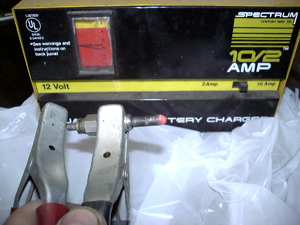
- If you have the plugs out of the vehicle. I test mine with a 10A battery charger as pictured above:
- Note, this is a fast glow plug, as indicated by the brass-colored terminal
-
Why a 10A charger?
- Mine has a 2A and 10A range
- 2 amps is unlikely to provide enough current to heat the plug up, resulting in a false negative reading
- So I used the 10A range, you can use a higher output charger
- New "smart" battery chargers may not work for this test as they want to sense the battery volts. This charger is an old "dumb" charger.
-
No battery charger?
- Then just use a small jumper cable (connected to the negative battery terminal) to hold the plug (like the black clamp pictured) and touch the threaded end of the plug to the positive battery terminal.
- Pull the plug from the engine
- Clamp the plug body in the negative clamp and touch the positive clamp to the plug terminal
-
If it doesn't glow red hot in a few seconds (or pull at about 10A)
scrap it
- IMPORTANT NOTE: Do not leave the plug connected to power any longer than needed to see that it glows. Doing so can cause an otherwise good plug to burn out prematurely.
-
I always replace all 4 plugs if I suspect one or more is defective
- They are such a pain to remove and reinstall, I'd rather do them all at once and have new ones in there
- I do keep the working old plugs around for spares.
- I think I now have enough to do a replacement.
- Another option is to use new plugs in the two hardest-to-reach locations and re-use the old, working plugs in the two easy-to-reach locations. If they later fail, they can be easily replaced.
-
What are symptoms of failing glow plugs?
- I find that with one bad plug, starting is not too hard, I get a bit of smoke and rough idling
- When I get down to 2 plugs, it is time to replace them
-
Once had the 2nd and 3rd plug go at about the same time
- On one plug, starting is darn near impossible if it gets cold
- If you do get it running, you'll be blowing an enormous cloud of thick smoke for many minutes before the engine warms up enough to drive
-
Also. TEST THE NEW GLOW PLUGS before you put them in the engine
- It only takes a few minutes and you already have everything set up (to test the old ones, right)
- New only means the glow plug has not been used before, doesn't mean it works!
- Here is my detailed glow plug article with specifications and troubleshooting information
- Here's a good write-up on glow plug troubleshooting
 ===>>
===>> 
[Last updated: 19.August.2021]
![]()