
VW A1/A2/A3 Shift Linkage Installation
Download or print a copy of this web page for use during installation.
Or here is an Adobe PDF file of these instructions that you can download.
A1/A2/A3 Transmission/Shift Linkage Kits:
- Introduction
- Short Throw Arm Installation
- Weighted Shift Rod Installation
- MissingLinkZ Shift Linkage Installation
- Relay Shaft Bushing Replacement
- A1/A2/A3 Shift Rod Bearing Replacement
- A1 Relay Lever Ball Replacement
- A2/A3 Relay Shaft Ball Cover Replacement
- Ball Stud Replacement and Heim Joint Installation
- 4->5 speed selector lever extension installation
- Neoprene Washer Installation
- A1 Relay Lever Shim Installation
- Shift Linkage Tune-up
Introduction:
If you look closely at the water-cooled VW shift linkage, it is truly a marvel of mechanical design. It transmits the front-back and side-side motion of the shift lever on the floor of the vehicle into motion on selector shaft of the transmission, to allow shifting gears. Front-back motion of the gear shift is transferred as back-front motion of the shift rod which in turn is translated into left-right rotation of the relay shaft which in turn is translated into a rotation of the selector shaft. Side-side motion of the gear shift is converted to rotation of the shift rod, which is converted to a left-right motion of the rear selector rod then to a front-back motion of the front selector rod which pushes and pulls on the selector shaft of the transmission. Click on the images below for a detailed view of a typical A1 or A2/A3 shift linkage:
 |
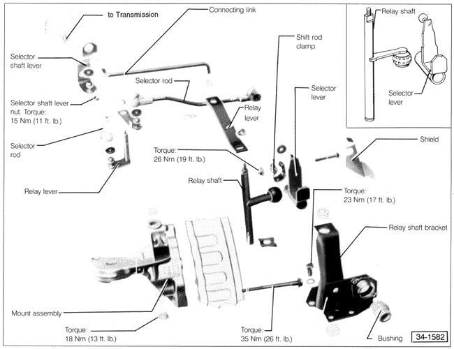 |
| A1: Shift Linkage Diagram | A2/A3: Shift Linkage Diagram |
See the following sections for information on replacing/upgrading various parts of the shift linkage...
[Return to the top of this page]
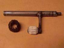
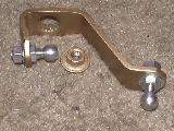
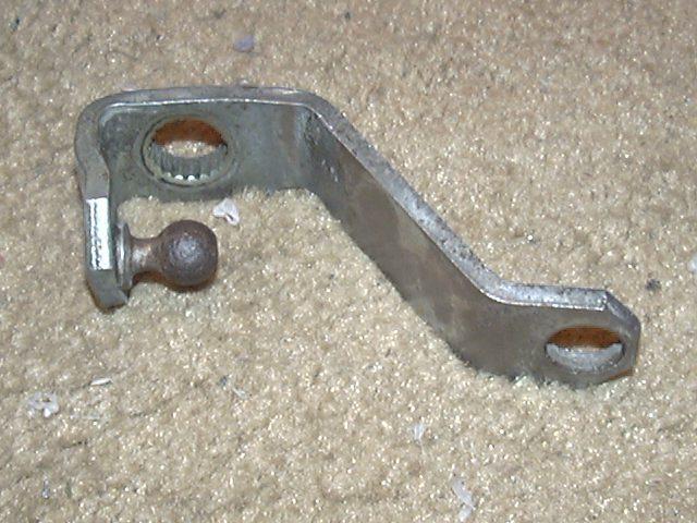
Short Throw Arm Installation:
 |
| Short Throw Shift Arm Installed |
- Set the parking brake and place the transmission in neutral, open the hood
-
You may want to remove the relay shaft for ease of installation
-
A1: Remove the nut that retains the shift ball at the base and the clip
that retains the shift rod at the top, if replacing the pivot bushings.
- Or you can just do the upgrade on the lever in place if only installing the short throw arm
- A2/A3: Remove the nut at the top of the relay shaft that holds the shift arm in place
-
A1: Remove the nut that retains the shift ball at the base and the clip
that retains the shift rod at the top, if replacing the pivot bushings.
-
Remove the bushing that the shift rod inserts into
- If the bushing is hardened from age, try soaking it in very hot, soapy water to soften and lubricate it
- Use a flat blade screwdriver to press in at the base of the small end of the bushing to collapse it and push it through the hole
-
If all else fails, you can cut off the small end and press it out of
the hole
- If not installing a complete Missing LinkZ kit, then it would be necessary to replace the bushing
- Place the extension on top of the lever and the clamp on the bottom
-
Tighten the retaining nut and torque it down to approx. 20-30 ft-lbs to
securely clamp the extension to the lever
- Make sure there is no side to side play in the extension, if so, re-tighten it.
- Be sure and re-check the fastener after approx. 100 mi. or km of driving.
-
Re-install the bushing at the inner hole for a ~25% reduction or the
outer hole for a ~50% reduction, insert the rod and insert the
retaining clip
- If the old bushing was damaged, consider replacing it with a new one
- If installing the full Missing LinkZ kit, there is no need to re-install the old bushing, it is no longer needed
- If the relay shaft/arm was removed, replace it and make sure all the fasteners are tight
-
Lower the hood and give it a test drive, it may take a few days to
adapt to the new and improved feel of the shifter
- I encourage you to start at ~25% and try it for a few days
- Then try the ~50% position for a few days
- Pick the reduction level you like the best
- You can also remove the extension to revert to the stock shifter travel
-
On some vehicles, you may experience interference with the lengthened
relay shaft arm; hitting the turbo, for example
- If so, you can often bend the relay shaft arm a bit to clear the obstruction
NOTES:
- There is supposed to be some room around the stud welded into the U-shaped clamp and the hole in the relay shaft arm, the bolt is 11mm and the hole is 14mm.
-
The U-shaped clamp may be a snug fit over the relay shaft arm. It may
spread out a bit as you tighten down the nut on the bolt.
- The clamp around the sides of the relay shaft arm and the short throw extension that hold the two together, the bolt simply holds the clamp in place.
- If you removed the relay shaft to install the short throw arm, be sure to properly tighten the nut holding the relay shaft in place, perhaps even use some thread locking compound.
[Return to the top of this page]
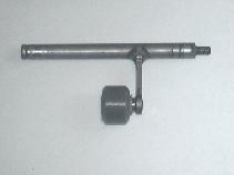
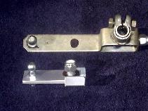
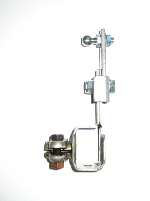
Weighted Shift Rod Installation:
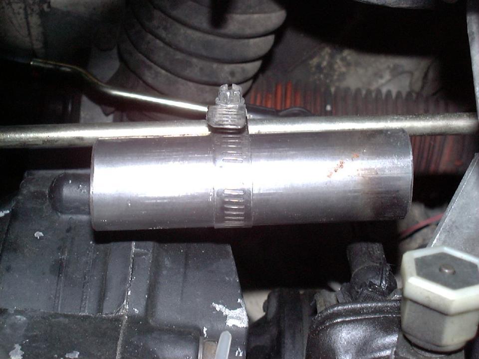 |
| Clamp-on Shift Weight Installed |
- Set the parking brake and place the transmission in neutral, open the hood
- Open up the hose clamp so that you can fit it around the shift rod (alternately, you could pop one of the shift rod ends loose)
- Place the groove in the weight along the shift rod and slide the clamp over the weight, roughly in the center
-
Tighten the hose clamp down and check for clearance by manually
shifting the linkage into all the gears
- You may want to run a bead of sealant along the groove in the rod to held hold it in place if the clamp loosens up
- Lower the hood and give it a test drive, it may take a few days to adapt to the new and improved feel of the shifter
For installation of the billet weighted shift rod, information, see the Missing LinkZ installation section.
[Return to the top of this page]
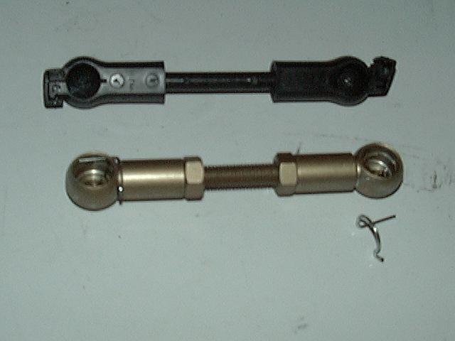
Missing LinkZ Shift Linkage Installation:
The shift linkage consists of one to three fully adjustable links which will replace the same length stock link. The links are not pre-adjusted to length. You will set each link to the length of the stock link it replaces. This is done so that you will feel comfortable with the length adjustment procedure so that if needed, you can fine tune the individual links as needed. The installation procedure is listed below:
- Set the parking brake, block the wheels if you are on a hill and place the transmission in neutral, open the hood
- If needed, remove any obstructing items like air ducts, etc. to allow easy access to the shift linkage parts behind the trans-axle
-
Locate and identify the shift linkage components, the rear and forward
selector rods and the shift rod
- Go ahead and work the linkage by hand through all the gears so you get a feeling how it is supposed to work
-
Pick one link, release the plastic
clips and pop the link off the ball stud
- By replacing one link at a time, you should have a functioning linkage at all times and won't have to worry about where a given part is supposed to go
-
Lay the stock link and the corresponding adjustable link beside it and
turn the rod ends in or out to adjust the length to match
- Try and keep the adjustment balanced between the two rod ends to ensure adequate thread engagement on both ends
- Some links have offset ball studs, so be sure to match the orientation of the stock link
- Once set, tighten the jam nuts to hold the rod ends in place
-
Remove the retaining clips from the rod ends and pop them on the
corresponding ball stud
- The rod ends are pre-greased with white lithium grease for your convenience
- Repeat the above steps with the other selector rod
-
For the forward shift rod, you have a few options.
- It can be installed with the existing rubber bushings in place or the bushings can be removed
- If the bushings are old and hard, just insert the ball stud and tighten down the nut, perhaps add a washer if needed
-
If the bushings are fairly soft or you wish to remove them, do so and
insert the ball stud w/ upper
and lower washers and the thick metal bushing to fill the
hole left by the rubber bushing and tighten down the nut.
- Use the supplied washer and feel free to apply a thread locking compound to the threads, tighten to 10-13 ft.lb.
- See the installation detail below:
- If installing the ball stud in the bolt-on short throw shift arm with small holes, the ball stud will fit w/o need for additional bushings.
- You probably will have parts left over, depending on how you install the ball studs.
-
Note, there is no difference in installing the billet
weighted shift rod or the non-weighted adjustable rod.
- In either case, set the length and orientation of the rod ends to match the stock rod, pop it over the ball studs and install the safety clips.
-
Again, run the linkage through all the gears and make sure there is no
binding and that it is all put back properly
- You should make sure that none of the gear shift motions try to "over-shift" the transmission, i.e. pushing it past where the gears engage. On the 020 transmission, 3rd gear is particularly vulnerable to over-shifting.
- Lower the hood and give it a test drive, it may take a few days to adapt to the new and improved feel of the shifting
-
Make any length adjustments as needed and once you are happy with the
shifting, go ahead and install the retaining clips on all the rod ends:
-
If needed, make small changes in lengths to the various links by
turning one rod end in or out one turn (1.25mm) at a time and then test
the shifting. If more than one turn is needed, be sure to turn the
other rod end for the 2nd turn to keep the thread engagement equal.
- Tighten down the jam nuts after finished making changes.
- To hold the rod end while tightening the jam nut, you can fit an open end (16mm or 5/8") or adjustable wrench over the flat of the rod end.
-
NOTE: One sign of improper length adjustment is
the inability to reach all gears,
see this section on Length Adjustment for more info:
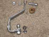
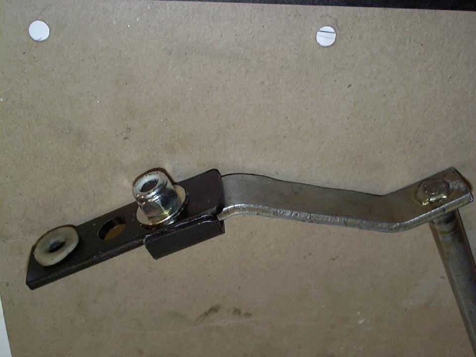
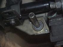
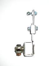
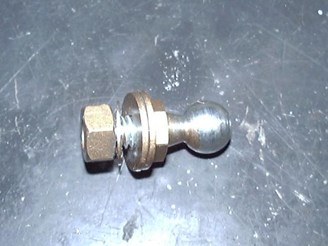
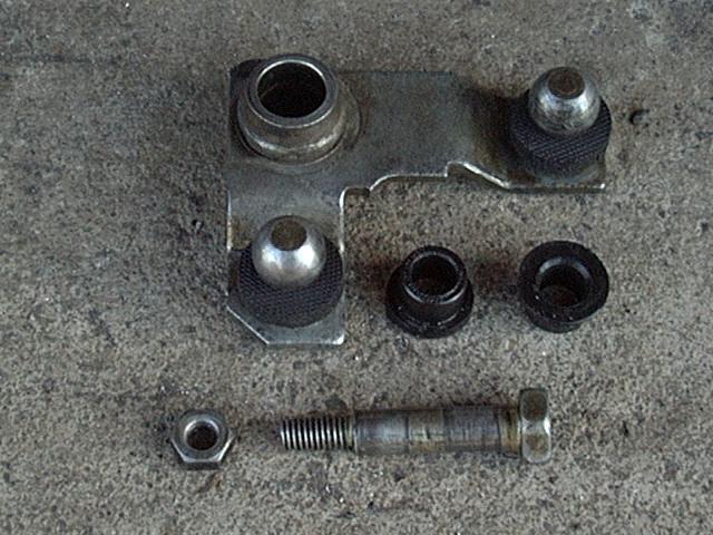
Ball Stud Installation Ball Stud Installation:
Shown above is an A1 Selector Lever (removed from the transmission for clarity - A2/A3 installation similar) showing the OEM poly bushing (yellow) removed and the ball stud, steel bushing, washer and lock nut ready to install in its place. Other installation options include using the larger washers (supplied) with the steel bushing, or if removal of the poly bushing is not desired, the ball stud can also be installed in the poly bushing. Installation of the ball stud on the relay shaft (or short throw shift) arm is identical. There is no one right way, you may have parts left over, we try to include enough hardware to handle various situations. And no need to remove the part from the vehicle for installation, we only did so for ease of taking a picture.
- IMPORTANT NOTES:
-
Be careful when starting the nut on the bottom of the ball stud to
avoid cross-threading it.
- Due to the location/orientation of the parts, you have to start the nut in an awkward position, so make sure the nut spins freely onto the threads below the ball stud.
-
Be sure to fully tighten the nut on the bottom of the ball stud to seat
the washer.
- Use a wrench on top of the stud and a wrench below, apply 10-13 ft.lb. torque.
- For added security, use a drop of red Loctite on the threaded end of the stud to help keep the nut fixed in place.
- Be sure and re-check the fastener after approx. 100 mi. or km of driving.
Missing LinkZ Maintenance:
Once installed and adjusted, the Missing LinkZ need little routine maintenance. Once every year or two, you might want to remove the retaining clips, pop each link off, check for any abnormal wear and apply a small amount of lithium or moly grease in the ball socket and reinstall it.
[Return to the top of this page]
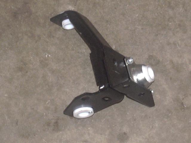
Relay Shaft Bushing Installation:
Bushings installed in bracket A1 relay shaft from below Pictured above is new bushings installed in an A1 relay shaft bracket, on the left is from the top looking down, on the right is from below looking up.
-
Since the bushing material is rigid, you can't "squeeze" it
into the bracket hole like the OEM polyurethane version. Instead, the
bushing it turned to the exact size of the hole. If you find it too
difficult to press it in place, a radial slit can be cut in it to allow
it to be compressed a bit to fit into the hole. When the relay shaft is
inserted, it'll expand and lock into place in the bracket.
-
Likewise, if you find the bushing fits your shaft a little too loosely,
you can also cut a fine slit in it like pictured and then wrap the
outside of the bushing in some good quality electrical tape or a wrap
of fine gauge wire to close the slit tighter.
- Use a fine saw blade like an Exacto blade or razor saw, not something like a carpentry saw.
- If you use tape, that will both increase the OD of the bushing (so it fits tighter in the relay shaft bracket) and shrink the ID by compressing the slit. If you use a few wraps of fine gauge wire, you'll only be shrinking the ID of the bushing. Where to get fine gauge wire? Easy, cut a length of stranded wire, remove the insulation and pull out a strand or two of the copper conductor.
- You do not want the bushing so tight that the relay shaft binds up and is not free to rotate. A little bit of play is better than so tight it can't turn. And with the two relay shaft bushings separated vertically, a little play at each bushing will not result in a large amount of slop in the relay shaft itself, due to the vertical separation.
-
Likewise, if you find the bushing fits your shaft a little too loosely,
you can also cut a fine slit in it like pictured and then wrap the
outside of the bushing in some good quality electrical tape or a wrap
of fine gauge wire to close the slit tighter.
- A small screw serves to keep the bushing stationary in the bracket while the shaft rotates in the bushing.
We have observed minor variations in relay shaft diameters, some are 14mm, some aftermarket ones are 9/16" and they can vary between A1 and A2/A3 vehicles. So, we drill the center hole in the bushing to fit properly on the smallest OD shaft we've found. If it feels a bit tight on another shaft, it is a simple matter to use a file or a roll of sandpaper to slightly enlarge the bushing to fit properly. We also find that an application of a graphite or moly grease to the inside of the bushing helps both installation and initial operation.
See notes on the A2/A3 installation in the following section.
- Remove the 13mm nut on the bottom of the relay shaft and wiggle the shift ball/arm off.
- Pull off the shift rod on the top the relay shaft and lift the shaft up and out of the bracket.
- Remove the old bushings and clean up the bracket if desired.
- Install the bottom bushing from the bottom, align the screw with the notch in the bracket.
- Install the top bushing from the top, again align the screw with the notch.
- The relay shaft is then inserted into the top then bottom bushing and the lever is reattached to the bottom.
- Check to make sure the arm can pivot freely before reattaching the rest of the linkage.
- It is a good idea to use some thread locking compound on the retaining nut.
- On the A2/A3 relay shaft, there is a clip on the bottom and the nut is on the top, but the bushing installation is identical, see the following section for details.
Notes:
- On the A2/A3 if you need to replace the "orange" shift rod bearing on the main shift rod, it is easier to unbolt the entire relay shaft bracket (3 bolts) from the steering rack and take it out of the vehicle, then replace the orange bearing and the relay shaft bushings before re-installing it.
- If removing the clamp on the main shift rod, be sure to mark its location before loosening the clamp to aide in putting it back when finished.
- If you are installing the short throw shift arm, that is best done while the relay shaft is out of the vehicle.
While taking the above pictures, I removed my year old UHMW bushings and once cleaned of oil and grease (my engine has an oil leak and I just had an inner CV explode) they could pass for brand new. No discernable wear or play in the bushings. Only reason I removed them was to test the new Teflon bushings. I did notice a small difference in feel between the UHMW and Teflon, with the Teflon giving a bit lighter feel to the shift. I also did not need to apply any grease on the Teflon bushings like I did with the UHMW. But if you want to add grease or other lubricant, feel free. What kind? Anything you want to or have on hand. Both UHMW and Teflon materials are pretty much inert to most lubricants and solvents. Only items to avoid are things like benzene, ether, methyl ethyl ketone, etc.
[Return to the top of this page]
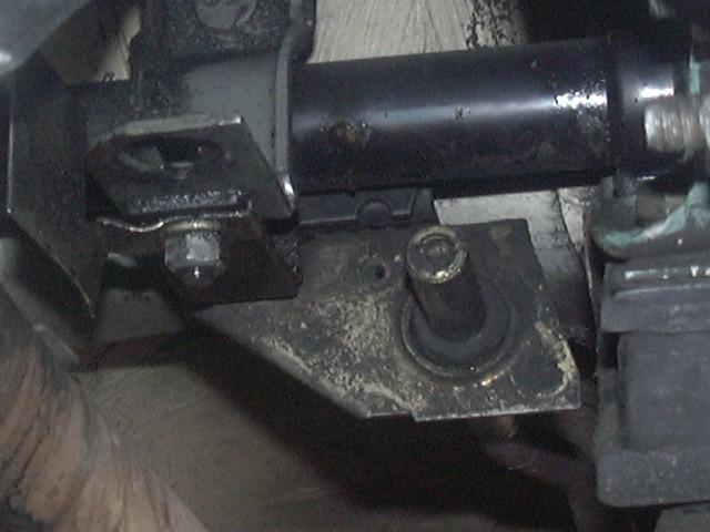
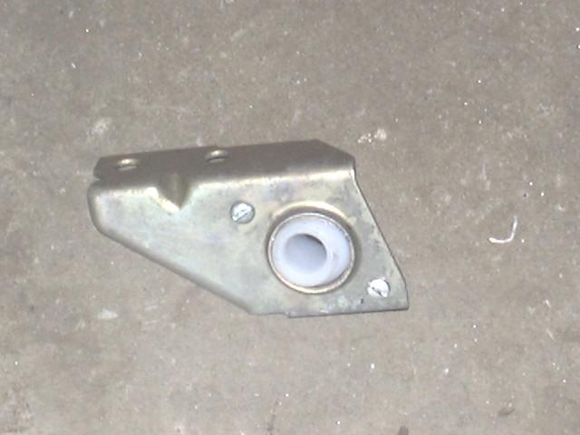
A1/A2/A3 Shift Rod Bearing Replacement:
In the A1 chassis, there is one bushing that is located inside a steel bracket called the shift rod bearing. It is not designed for replacement without replacing the entire metal bracket, at least until now!
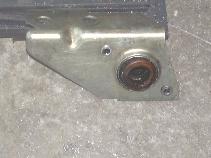
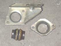
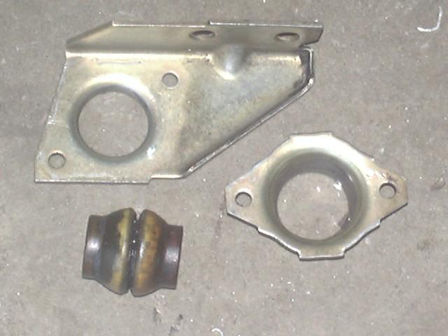
A: Worn shift rod bearing B: Shift rod bearing removed C: Bearing disassembled 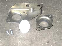
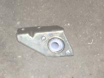
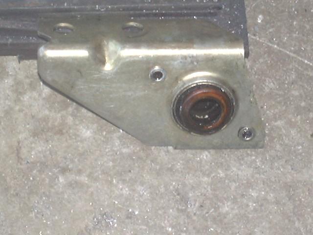
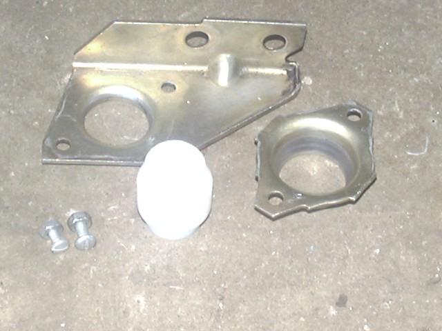
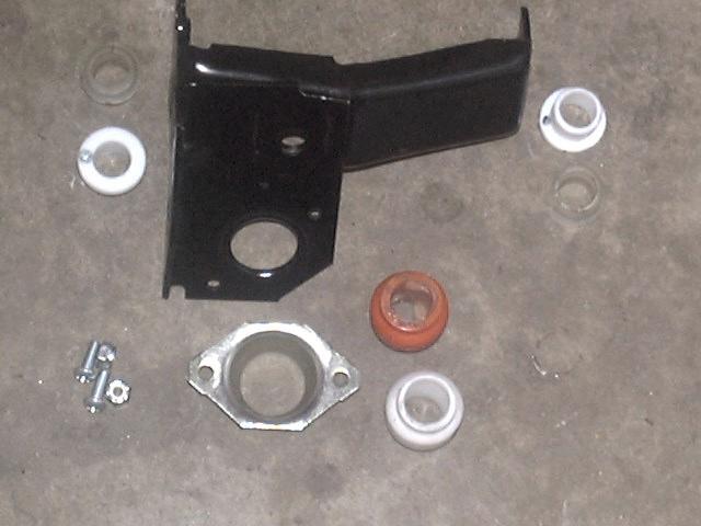
D: New shift rod bearing E: New bearing assembled F: New bearing installed For the A2/A3 chassis, the shift rod bearing is located in the relay shaft "tower". It is easiest to remove it from the vehicle and repair it on the bench:
A: A2/3 Shift Rod Bearing Install B: A2/3 Shift Rod Bearing Installed To install the new bushing, the old bushing and bracket must be removed from the vehicle. Assuming the selector lever has been un-clamped and removed (be sure to mark it for ease of later installation and shift linkage alignment) from the shift rod (image A), remove the pair of 13mm nuts that hold the bracket to the steering rack bracket. Clean the bracket (image B), drill (7/32" or 5.5 - 6mm bit) or punch out the 2 rivets that hold the bracket together (image C). Then install the new bushing (image D) and screw the bracket back together with the supplied screws (image E) and then install the refurbished shift rod bearing into place. The shift linkage will then need to be aligned as discussed elsewhere in this document.
You can follow the procedure in the Bentley shop manual for reinstalling the Selector Lever onto the end of the main shift rod. Or the technique we use is to put the transmission in neutral, gear shift in neutral and make sure it's standing straight up. Then slide the Selector Lever onto the splined rod, making sure the lever arm is vertical. Forward and back on the rod only affect where the gear shift knob is in the car. If you want to move the knob forward or back, you can adjust where the Selector Lever clamp is on the end of the rod. With our adjustable shift linkage, you can make small (1.25mm) length adjustments of the various shift rods as needed. If you don't have out adjustable linkage rods, you may need to adjust the Selector Lever by rotating it slightly on the end of the shift rod. Towards the left will help with R-1-2 gear selection and to the right will help with the higher gears. Only make small changes in the angle of the lever. Usually no more than 1/8" or 3mm movement of the ball stud on the end of the lever is all that's needed.
- Adjustment:
- If the shift rod bearing is too tight inside the bracket, you can slightly loosen the screws holding the two halves together. A thin washer can also be inserted in between the bracket halves.
- If the shift rod bearing has a little too much play inside the bracket (usually due to rust or corrosion of the bracket body), a 1" ID, 1/16" dia. rubber o-ring can be slipped over the bearing before slipping it between the bracket halves. The o-ring will fill up the space inside the bracket. Alternately, a silicone or butyl rubber sealant could be applied to the inside of the bracket to hold the bearing more snugly once the sealant cures. The sealant will provide the compliance needed to allow the bearing to move inside the bracket, which it needs to work properly.
[Return to the top of this page]
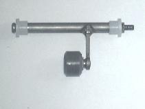
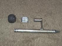
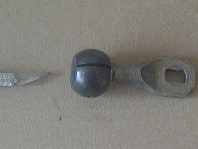
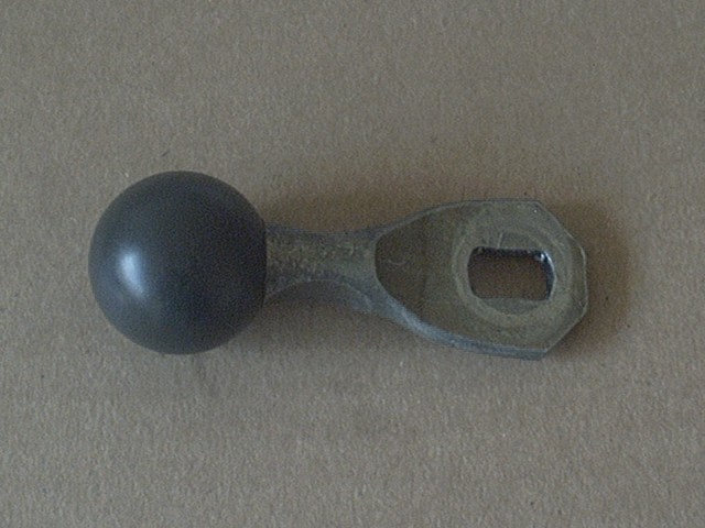
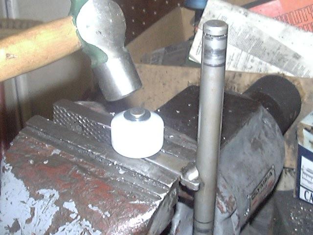
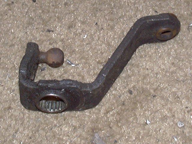
A1 Relay Lever Ball Replacement:
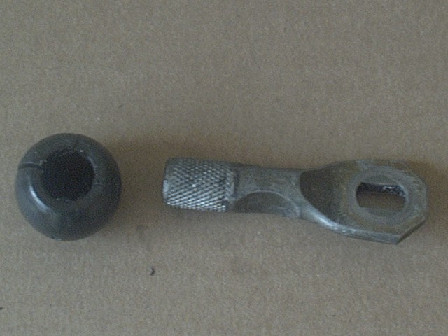
Remove the existing relay lever from the bottom of the relay shaft. Easiest to access from beneath the vehicle. Typically held in place with a 13mm nut and lock washer (save for later reuse). With the relay lever removed from the vehicle, you may need to slit the remnants of the rubber ball end with a utility knife (photo A, below). To ease cutting you can dip the blade in water or light lubricating oil. Usually you'll need to make a few passes to slice down to the center of the ball. Once slit to the center, peel the rubber ball off the end of the lever (photo B, below). You'll probably find that there is a layer of rubber stuck to the knurled end of the relay lever. The easiest way to remove that is to heat up the relay lever end with a heat gun or propane torch, to the point the rubber just starts to smoke. Then, hold the lever in a vise or pair of pliers (it may be hot) and use a cloth rag to twist the rubber residue off the end of the lever, it should come off fairly easy. If some remains, reapply the heat the wipe again. The cleaned lever end should look like the one in photo C, below.

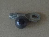
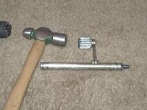
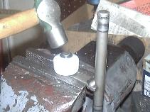
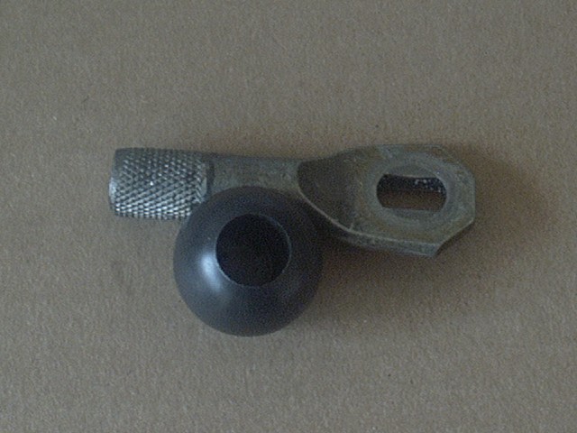
A: Cut rubber relay lever ball B: Remove rubber ball C: Clean Relay Lever end Then, place the hole in the Delrin ball over the end of the relay lever and press it onto the knurled end until it bottoms out. It's supposed to be a tight fit, but if it is too tight to install easily, you may need to file down the knurling on the end of the shaft for an easier fit. You can use a rubber mallet or dead blow hammer to do this, or place the ball onto a piece of wood and use a hammer to drive the shaft into the ball. The finished assembly is shown in photo E, below.
If you find your relay lever end is worn to make the fit of the ball loose, feel free to use a good grade of high temperature epoxy glue or a polyurethane construction adhesive on the knurled section before pressing the ball in place. Since this part is fitting over the internal surface of the relay lever shaft, it is not required to be exactly the same diameter as the original VW part. There are many aftermarket parts suppliers and as long as the overall length and ball diameter is right, they can do anything they want with the inside dimensions and since they mold the rubber ball on the end, it is always a perfect fit no matter the size of the metal section. So if the replacement ball makes a nice friction fit, great. If it fits looser, glue it in place.
Short of having each and every customer use a micrometer to measure their relay lever shaft diameter before ordering, we have to pick one hole size to machine in the Delrin ball. Heck we even have trouble getting customers to specify 5-sp. or 4-sp. shift linkage styles on our A1 kits. We chose a size that fit our OEM VW relay lever. Nothing wrong with having to glue the ball in place, in fact you can add glue even with the tighter fit if you prefer the "belt and suspenders" approach. We can't guarantee a perfect friction fit on any random relay lever, it took us about a dozen different off size milling cutters to find one that drilled the right size hole to fit our OEM relay lever. But since that part is knurled, the final OD can vary a little and even 0.001" difference can affect the friction fit. If you are planning to glue the ball in place, you might want to drill a tiny air release hole (1/16" - 1/8") through the bottom of the large recess to allow trapped air to escape. The adhesive may seal up the knurling and cause air to be trapped inside as you push the ball in place. Normally that air can escape around the knurls.
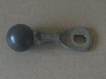
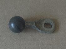
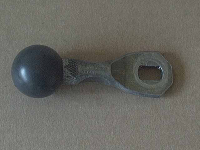
D: Drive Delrin Ball on end of Lever E: Completed Relay Lever assembly Once complete, re-install the relay lever on the bottom of the relay shaft. Torque the nut to the value specified in the Bentley repair manual, approx. 15 ft.lbs. You may want to check that nut for tightness after a few hundred miles of driving and you might consider using some thread locking compound on it as well.
[Return to the top of this page]
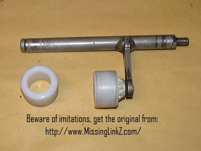
A2/A3 Relay Shaft Ball Cover Installation:
Note that the current ball cover color is gray, although this can change back to white depending on material availability. Both the gray and white covers are equally functional, they install the same way and work alike.
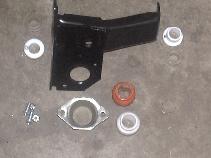
A: A2/A3 Relay shaft w/ worn ball B: Worn ball slit and removed C: A2/A3 ball cover pressed on 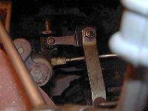
D: Worn A2/A3 relay ball
E: New UHMW A2/A3 relay ball
F: A2/A3 Relay Shaft Bushing Set INSTALLATION:
-
To install the new bushing, the relay shaft should be removed.
- See photo D above for the pre-installation.
- There is a small spring clip at the bottom of the relay shaft that can be pried off with a small flat blade screwdriver, this is most easily accessed under the vehicle.
- A 13mm nut holds the arm to the top of the relay shaft needs to be removed and can be accessed from the top of the engine compartment.
- After removing the nut, un-clip the rear selector rod and set it to the side.
- You can now lift the relay shaft straight up and out of the relay shaft bracket, see photo A above.
-
The old ball material must be removed from the nylon core (if any is
present).
-
To do so, slit the polyurethane and rubber with a sharp knife or razor
blade cutting into one of the spline grooves.
- If the blade sticks in the rubber, you can apply a small amount of lubricant to the blade (WD-40 works well).
- The flexible outer layer can easily be peeled back and removed, see photo B above.
-
Clean up the relay shaft then press the new UHMW-PE bushing over the
nylon core until it is fully seated, see photo C above.
- Usually can be done pressing the ball cover on with your thumbs with the base of the pivot on a solid surface.
-
To do so, slit the polyurethane and rubber with a sharp knife or razor
blade cutting into one of the spline grooves.
-
You are now ready to reinstall the relay shaft.
- If replacing the relay shaft bushings, place one in the bottom bracket , then insert the bottom of the shaft then press the upper bushing down over the shaft into the bracket.
- Push on the lower clip from underneath the vehicle.
- Install the arm on top of the relay shaft and tighten down the nut.
- See photo E above for the completed assembly.
-
Normally the friction fit is plenty to hold the ball cover in place.
-
If you find the fit of the ball cover on the plastic core is a bit
loose, feel free to apply some adhesive or sealant to hold the cover in
place:
-
First clean both surfaces well with a suitable solvent, let dry then
apply the adhesive. A polyurethane construction adhesive, "Automotive
Goop" or something like an ultra-black or
ultra-gray RTV designed to resist engine oils should do the job.
- Just run a bead around the top and bottom of the ball cover, the material will bond to the ridges in the nylon core and prevent the cover from moving up or down or apply around the body of the nylon core and then slide the cover over and let the adhesive cure.
-
An alternative is to use some heat shrink tubing over the nylon core.
Tubing will be sold with before and after diameters listed, you want
something large enough to fit over the ~21mm dia. core (pre-shrink dia.
> 21mm) and something that will shrink down to that dia. (after
shrink dia. < 21mm).
- The larger the pre-shrink dia. you start with, the thicker the shrunk tubing will be. We find that going with tubing a bit larger, say 1"/25mm will give you about 1mm larger dia. on the core, remember you get double the tubing thickness as it sits on both sides of the core.
- Shrink the tubing on with a heat gun, lighter or even a regular oven set on the lowest temperature works. We use an oven set to 225-250*F and let the part sit in there for 10 minutes or so until the tubing shrinks.
- Another alternative for building up a too small core would be to use a self-fusing silicone tape. This is a stretchy silicone rubber tape that bonds to itself without an adhesive. It applies like a regular electrical tape, but you can stretch it for a tight fit and it'll fuse to itself over a period of time to make it like one solid piece. Advantage of this is you can add a layer at a time to build up the outer diameter.
-
First clean both surfaces well with a suitable solvent, let dry then
apply the adhesive. A polyurethane construction adhesive, "Automotive
Goop" or something like an ultra-black or
ultra-gray RTV designed to resist engine oils should do the job.
-
If you find the fit of the ball cover on the plastic core is a bit
loose, feel free to apply some adhesive or sealant to hold the cover in
place:
-
Alternately, if just replacing the ball cover only, you may be able to
remove the lower clip and then slide the relay shaft up and out far
enough to gain access to the ball.
- This way you do not need to remove the upper nut and arm.
-
In either case, be sure the clip (and nut if removed) are reinstalled
properly.
- If either of those parts come loose, the shift linkage can fall apart while driving and you'll be unable to shift the transmission.
- Photo F shows the placement of the new bushings on the A2/A3 relay shaft.
-
Although the UHMW material is self-lubricating, you can apply a coating
of any type of grease to the ball if you wish, to help smooth out the
shifting operation.
- The ball cover is made to be a snug fit, you could also sand down the cover or bend open the sides of the cage the ball sits within if you find the fit a little too snug.
- Likewise, if the fit is too loose, you can bend in the sides of the cage that retains the ball for a tighter fit.
This part is designed to be tweaked for a perfect fit on your vehicle. Now if we had your car sitting in our shop, we could measure and test fit parts to get a perfect fit, but your car is not sitting in our shop. We can only make a part that should fit most vehicles out of the box, but some may need some fine tuning. And if you want to eliminate the nylon core on the relay shaft, see our replacement ball option below. It's a little more expensive and a bit more work to install.
Notes:
- The ORANGE shift rod bearing pictured in "E" above, is not included in the shift linkage kit. If this part is worn, a new part can be obtained here.
- If your relay shaft ball is worn to the point that the inner nylon core is chewed up, we can custom drill in inside of the bushing to fit a smaller than normal (21.5mm) core. The replacement "ball cover" relies on a tight press fit for installation.
- IMPORTANT: If the inner nylon core is loose enough to slip off the pivot stud on the relay shaft (picture G below), you can use a hammer to peen over the end of the stud (to flare or mushroom it out) to hold the core in place (picture H below). Just place the base of the stud on a solid surface and work your way around the edge of the stud with the hammer to bend (or peen) it over to create a lip to keep the core from slipping off.
[Return to the top of this page]
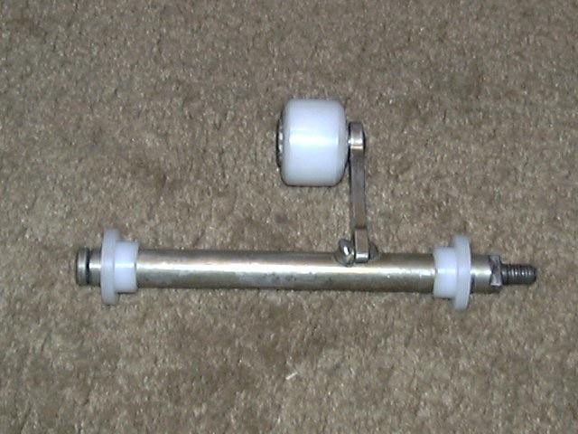
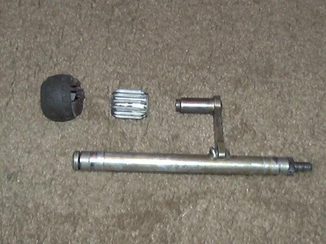
Relay Shaft Ball Replacement:
If the inner nylon core is so badly worn or even missing, a complete replacement ball is available (picture I), it slips over the stud on the relay shaft, then a small washer goes over the end before peening the end of the rod over to lock the washer in place. The full ball replacement kit includes the solid UHMW ball and retaining washer.
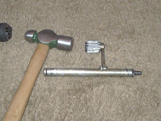
G: Loose relay shaft ball core H: Peening the end of the stud I: One piece ball replacement If the nylon core is loose or missing, you are half way there. If the nylon core is firmly attached, what works well is to fit the relay shaft into a vise (photo I above) or between two blocks spaced to hold the nylon core, but loose enough to let the shaft move. Then use a hammer and punch to drive the pivot pin down and out of the nylon core. It is held on with an internal lip that catches on the top end of the pivot pin. Alternately, you could slit the nylon core by scoring it repeatedly down one of the grooves on each side, then split it in half.
Then, re-install the relay shaft and check the fit and operation. If you find the ball/cage fit is too loose, you can bend the sides of the cage in a little bit or if the fit is too tight, they can be bent outward a little bit as needed. You want to make sure there is no binding of the relay shaft as it swings about the vertical axis.
[Return to the top of this page]
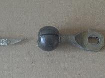
Ball Stud Replacement and Heim Joint Installation:
VW uses 13mm ball studs for ends on two of the shift linkage components. Over time and due to lack of lubrication, these ball studs can become corroded and/or worn.

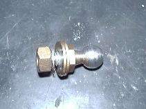
If your ball stud looks like this... You need to replace it with this To replace the ball stud, you must remove the linkage piece that that stud is attached to. The factory ball studs are usually pressed into place and then welded on the back side. So you can try grinding off the back side weld bead and then press out the old stud. Or you can drill out the ball stud base (5/16" or 8mm drill bit) part way then use a punch to drive out the old ball stud. Then using the 5/16" or 8mm drill bit, ream out the hole for the new stud. Insert the stud and lock washer, tighten down the nut to 10-13 ft.lb. You can also use a thread lock compound as well and re-install the linkage end on the transmission. Don't forget to lubricate the socket with some grease before installing the socket. Below is how I rebuilt my trans-axle selector shaft:
1. Lever removed 2. Cleaned up 3. Drilling out ball stud 4. Parts for rebuild 5. Ready to install You can follow the steps above (holding cursor over each image will pop up a description of the procedure). Note that in images 4 and 5 (above) I pictured the selector lever with the ball stud for the Missing LinkZ shift linkage kit. Ball stud replacement doesn't require the Missing LinkZ to be used and rest assured that if you do order the Missing LinkZ linkage, the ball studs required for the basic installation are included. If you have some exiting studs that are worn, then order the replacements.
To reinstall the lever on the trans-axle, it should be pointing straight up when the shaft is in the middle position. The teeth on the splines are fairly coarse so it is not hard to find the correct orientation. While I've illustrated the procedure for rebuilding the selector shaft, the procedure would be the same for the ball studs on the relay lever or selector lever. Mine were in good condition, so I only replaced the worn one on the selector shaft.
- IMPORTANT:
- Be sure to fully tighten the nut on the bottom of the ball stud to seat the washer. Use a wrench on top of the stud and a wrench below, apply approx. 15 ft.lbs. torque. For added security, use a drop of red Loctite on the threaded end of the stud to help keep the nut fixed in place and check for proper torque after approx. 100 m. or km of driving.
The only differences in the above instructions for installing a heim joint linkage are:
- Instead of just replacing any damaged ball studs, you'll be replacing all the ball studs, one on the selector shaft on the trans-axle (as shown above), one on the selector lever attached to the large shift rod under the vehicle and 2 on the small relay lever (bell crank), so repeat the above procedure 4 times in all.
- Instead of installing a ball stud in the new hole, you simply install the bolt, washer and/or spacer through the heim joint and the newly drilled hole and install a lock nut below to lock everything down. Typically there will be the bolt, a washer, then the heim joint then a spacer or washer below that and then the linkage hole and finally a lock nut. The forward selector rod will just have a washer above and below the heim joint. The rear selector rod will have a short spacer above and below the heim joint and the main shift rod/weight will have a taller spacer below the heim joint to allow for clearance as the joints move through their range of motion.
- When tightening the nut on the bolt that holds the heim joint in place, you only want to make it snug with no play, so perhaps 5-10 ft.lb. of torque is plenty. You do not want to crush the joint and spacers with too much pressure.
[Return to the top of this page]
4->5 speed selector lever extension installation
1: Hybrid 4/5 Speed Lever 2: Selector Lever and Extension 3. Extension Installed In photo #1 above, you can see a sort of hybrid 4/5 speed selector lever as shown in the Bentley Repair Manual. I don't know if such a part ever existed, but the "A" ball stud shows where the 4-speed linkage attaches, while the "B" ball shows where the 5-speed linkage attaches. So to convert a standard 4-speed selector lever to the longer 5-speed part, you basically need to extend the lever to move the "A" ball stud up to the "B" location. In photo #2 above, you can see the bolt on selector lever that does just this.
To install the selector lever extension, when converting a 4-speed shift linkage to the 5-speed version, you'll need to grind/drill out the ball stud in the selector lever. This is best done with the selector lever removed from the vehicle. The process is identical to the ball stud replacement above. If you opted for the larger diameter bolt in the selector lever extension, you'll need to enlarge the hole left when you pressed out the ball stud. Likely you'll need to drill a 1/2" - 9/16" dia. hole in the end of the selector lever to allow room for the clamping bolt for the selector lever extension. For the smaller bolt, you may need to enlarge the hole to approx. 3/8" to insert the clamp bolt. The hole will be about where the black dot is in photo #2 (this is of course a 5-speed selector lever) and in the real 4-speed selector lever, the lever arm would end just past the end of the ball stud which was in the hole you just drilled out.
Photo #3 above shows the extension properly attached to the 4-speed selector lever.
Of course, if you have the 5-speed selector lever to begin with you would not need to do anything, since it is the correct part for the 5-speed shift linkage and trans-axle.
Once the stud in the extension clamp will fit over the end of the selector lever, you'll simply bolt on the extension arm in a fashion identical to installing the short throw arm. In the end, you'll end up extending the 4-speed lever from its ~2" length up to the 5-speed length of ~4" from the center of the clamp to the center of the ball stud. You can see in the above photo how the stud of the clamp fits into the hole in the 4-speed selector lever, then it and the nut hold the extension past the end of the lever and places the ball stud at the same length as the 5-speed selector lever. This added length is what lets the shift linkage "reach" 5th gear, which is beyond the normal 1-2-3-4 pattern.
[Return to the top of this page]
Neoprene Washer Installation:
The stock VW shift linkage rod ends have small rubber/neoprene washers that fit over the ball studs before the shift linkage rod ends are fitted. Those washers seem to have two purposes. One is to help to help to keep dirt out of the rod end socket where it could cause the plastic socket to wear out and become loose. And a second purpose seems to be that it helps to fill the space between the bottom of the ball stud and the socket to limit movement from engine vibration. The Missing Linkz metal rod ends will work fine with the OEM washers, but if yours have deteriorated, it is easy to install our replacement washers. Simply remove the linkage from the ball stud. Slip the old washer off (if present) and slip the new washer over the ball stud. It will be a tight fit as the hole in the washer is approx. 8mm and the stud itself is about 13mm in diameter. Once the washer is fitted, reattach the shift linkage end.
[Return to the top of this page]
Shift Linkage Tune-up:
Diagnosis:
So, how do you go about "tuning up" your shift linkage? The two enemies of any mechanical linkage are improper adjustment/alignment and excessive play/slop.
To find and eliminate the problem in the linkage, you must first find what it is happening and what is causing it. First off try and quantify the problem; for example is the problem only one gear, more than one, etc. Then try and determine what is different about the problem gear(s) and the ones that work. See where those gear(s) fall in the shift pattern, For example, are the problem gear(s) to the left or right of the pattern or to the front or back? Armed with this information, you can now pop the hood for a look at what is going on.
The best way to find out where the linkage is worn is to have a helper operate the shifter in the vehicle while you observe the linkage movement under the hood. Have your helper try to select a given gear and hold the shifter in position while you then try to manipulate the linkage at the trans-axle selector lever to see if it'll move farther. If it does, move the selector lever back and forth in this loose region between when the transmission is engaged fully and where the shift lever is held at. Watch what moves and what doesn't. The point at which the motion stops is where the play or slop is located. I.e. the linkage moves on one side of the source of play, but not on the other side, meaning the play or slop in the linkage as eaten up all the motion.
To better understand the causes of sloppy shifting, it is necessary to understand how the linkage is supposed to work. Any mechanical element naturally has 6 degrees of freedom (or motion), 3 translational (X, Y, and Z) and 3 rotational (roll, pitch and yaw). If you want that element to change one form of motion into another form, it must be fixed in one or more degrees of freedom to accomplish the transformation. And typically it should be fixed in all but the desired motion axis. So for example, the relay lever is supposed to only pivot about the vertical Z axis. Therefore, it should not have any side-side, front-back, up-down motion or any rotation about the X or Y axis, in order to function properly. So any motion in any of those other directions is not desirable and the source of that motion should be identified and minimized if possible.
For example the relay shaft converts fore and aft motion of the rod coming off the shift lever itself into rotational motion of the arm. In order for this transformation to happen cleanly, the shaft must be held rigidly in all three translational axes and only be allowed to rotate about its vertical axis. If the bushings on the shaft are soft or worn, the shaft can rack or twist in the bracket due to the forces applied to it. Any motion not directly converted to rotation about the vertical axis is essentially lost. Using a rigid material for the relay shaft bushings, like UHMW or Teflon, will prevent the shaft from racking, yet still allow it to pivot smoothly with little friction.
One other problem that is somewhat unique to the 020 trans-axles is problems with 5th gear. This is due to the internal design of the gear box and specifically with lubrication of the 5th gear components. If the gear oil level falls low enough, 5th gear can be left "high and dry". Initial symptoms can include popping out of gear (5th gear only) and also a burned or discolored quality observed when draining the gear oil. This is compounded by another design peculiarity of at least the "early" ('87 and older) 020 gear boxes. That is that the oil fill hole (used to check the gear oil level) is placed too low on the trans-axle housing to be used to detect the proper fill level. This is due to the angle that the trans-axle sits in the vehicle. Later trans-axle housings were redesigned to move the hole higher up for a more accurate fill level check. That said, you can always fill the trans-axle with gear oil (GL-4 grade is the best for this application) by volume (2 liters, or 2.1 qts.) and then find the amount of tilt to raise the driver's side for a proper level check. Generally a block about 1/2" - 1" tall under the drivers side tire will raise the level of the fill plug to check the level.
To check for play in the shift linkage, especially if you lack a helper to sit in the cab and manipulate the shifter, you can try locking the shifter in place. This could be done say with something heavy to strap the shifter to or a board across the front seats and some straps to tie the shifter in place. The general idea is that you want to restrain the shifter then manipulate the shift linkage under the hood to find out what moves. That is if the shifter can't move, then ideally none of the rest of the linkage should be able to move either. If some part of the linkage does move, then find out why and figure out what it would take to reduce that motion.
[Return to the top of this page]
Alignment:
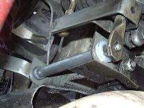
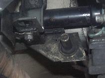
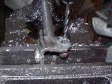
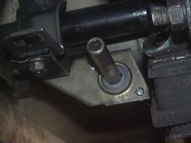
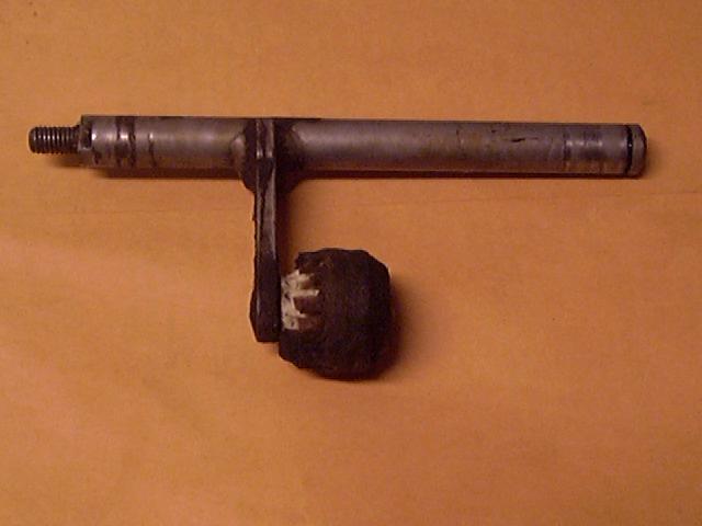
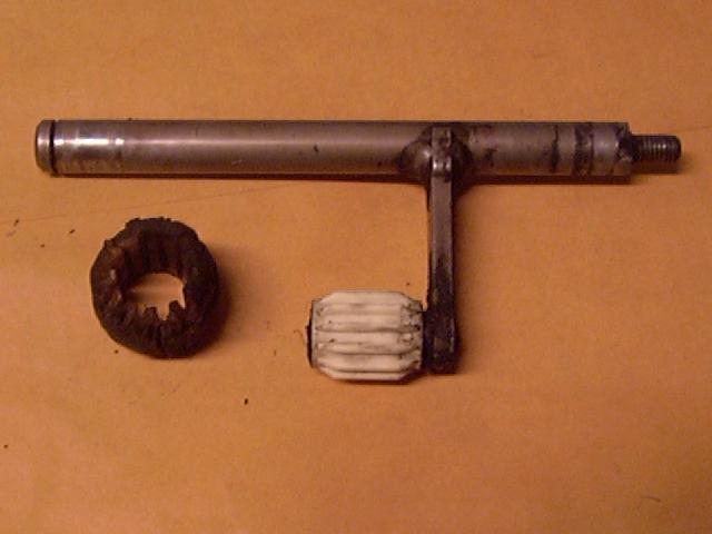
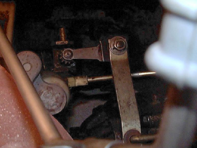
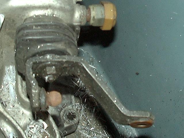
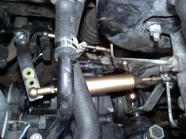
A key to proper shift linkage operation is alignment. This is especially important when changes are made to its geometry, such as using a shortened throw shift arm. In stock form, each link element was in direct alignment with its connecting element. As soon as an angle is placed in a link, instead of transferring 100% of the input motion to the output, you only transfer the cosine() of the angle of the link. This may not be directly apparent as "slop" but if you lose 5%-10% of the motion due to angularity, it doesn't matter where the motion was lost, it is not helping the transmission shift gears. An example of correcting alignment is shown below:
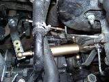
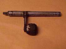
Stock configuration,
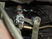
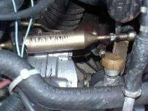
Rod behind selector shaftImproved alignment,
Rod in front of selector shaftBy moving the weighted shift rod from the back of the selector lever to the front, it changes the angle from about 15-20° to near zero, which eliminates about a 5% angularity inefficiency. Alignment applies to the entire shift linkage system, starting at the shift lever all the way to the selector shaft on the trans-axle. You want the shift lever centered in its range of motion so that you'll have maximum travel in all directions. If it is offset one way or the other, you'll be limited in that direction. In stock form, the only adjustment on the shift linkage is the location of the selector lever on the rod connected to the shift lever. Very small changes here have large changes in the linkage alignment. With a fully adjustable linkage, like the Missing LinkZ uses, you can make fine adjustments to each component independently to change alignment. If 1st and 2nd gear shifts are difficult, lengthen the rear selector rod as needed, etc.
[Return to the top of this page]
Excess Play:
So what's the big deal about "excess play"? Well, the shifter and linkage only have a fixed amount of motion that they can operate through. The transmission selector lever has a minimum amount of motion that it needs to select the various gears. If there is too much play, you won't have enough of the shifter motion transferred to the selector lever to properly shift gears. Therefore, it is best to have as little play, or wasted motion, in the linkage as possible.
Another area I found to be a problem in my A1, was the "relay lever". Mine was very loose and this led to a lot of play in the front and rear selector rods which attach to the relay lever. I found this play by using the above technique of moving the selector lever on the trans-axle and watching the rest of the linkage move. By moving the selector lever end of the linkage back and forth a little by hand, the point at which the motion stops is where the play is occurring. In my case, the selector lever and forward selector rod moved back an forth together, but I observed the relay lever racking on its pivot bolt, thereby absorbing the fore-aft motion. See the following section for a description of how the play was eliminated.
Conversely, too little play can be just as bad as too much. That is if the linkage is so tight that it binds up trying to reach certain gears, that can make shifting harder and cause to you miss shifts. As each vehicle's linkage will be in a different state of wear and adjustment, there is no hard and fast rule when you might run into binding. One common case is when adding a short throw arm onto an A2 or A3 shift linkage that is fairly tight (i.e. has fresh bushings, etc.) Since the A2/3 linkage is already a shorter throw (than the A1 linkage at least) to begin with, you may find that the short throw arm pushes the linkage too far out of alignment that it might bind up. A fix for this condition is to replace the forward shift rod with a rod end version. The spherical rod ends have much more angular capacity and also can allow for re-aligning the shift linkage as noted in this section. Binding could also be due to a lack of lubrication in some part of the linkage or it could be due to excessive play in an earlier section of the linkage that forces it out of alignment and forces the later part of the linkage to bind up. So a little detective work may be needed to find where the binding is occurring and why.
[Return to the top of this page]
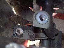
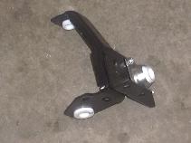
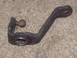
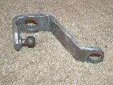
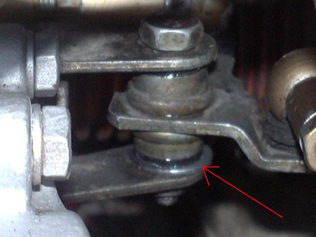
A1 Relay Lever Shim Installation:
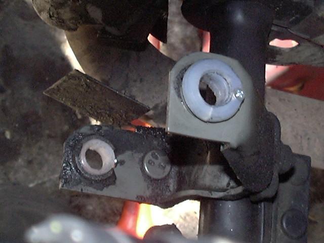
The relay lever is essentially a bell crank that converts east-west motion of the rear selector rod to north-south motion on the forward selector rod. When I had initially rebuilt my linkage with stock bushings, I had neglected this component, but it does have a pair of hard plastic bushings in it. I removed the nut and bolt that hold it in place and pulled it out for a look.

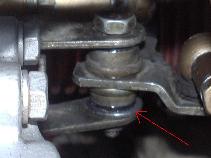
A1 Relay Lever Components Relay Lever with shim Instead of finding the bushings being worn (they were likely the 20 year old OEM bushings), I actually found that the length of the shoulder on the bolt was about 1 mm longer than the height of the lever and the bushings. Tightening the nut harder won't help as the shoulder on the bolt keeps it from getting any tighter. So instead, I took a flat washer and drilled it to fit over th shoulder and then installed the washer under the lever (see red arrow in photo above for location; with a little grease to let things move smoothly) and viola, the lever only rotates, no more racking, no more slop. And guess what, no need to push hard on the gear shift lever to get 1st gear and 2nd gear is no longer slow. If you need a washer set up for your A1 relay lever, links below to order one.
:
If you find the relay lever gets too tight after installing the shim, just remove one or both of the plastic bushings and lightly sand down the flange end to shorten them a bit. Test fit and repeat until you get a nice smooth fit.
Here's a 3D printable CAD file for the A2/3 Relay Lever Bushings to get rid of excess play.
Order a relay lever shim for US$1.00+shipping:
Add a shim to existing order US shipping International shipping
[Return to the top of this page]
Length Adjustment:
For a starting point, you can adjust the length of the adjustable shift rods to the length of the fixed shift rods you are replacing. If you don't have the old shift rods or are changing from say a 4-sp to a 5-sp trans-axle, the table below may help you in setting a beginning length. In the table, A is what Bentley calls the "Rod" or "Connecting Link" (i.e. the factory rod with the 2 bent ends). B is the rear selector rod (the one with 1 or 2 bends) and C is the front selector rod (the shortest link). Measurements are center-center of the sockets:
Link/Platform A1-4sp A1-5sp A2-5sp A3.5sp A 262mm 262mm 181mm 181mm B 170mm 173mm 203mm 203mm C 98mm 98mm 54mm 46mm Note: "?" indicates dimensions that are estimates, if you have an exact measurement of that factory link, send it to us and we'll update the table.
For the forward selector rod (C), its length should be set to match that of the factory part. Since it connects the relay lever (bell crank) to the selector shaft and both those parts are attached to the trans-axle housing, it probably does not need to be adjusted once it is set to the proper length, since the distance between its attachment points is unlikely to change. So all you want to do is make sure that as the selector shaft on the trans-axle moves in and out, the bell crank that the forward selector rod attaches to swings about the same angle forward and back. This will ensure that bell crank can move equally far in both directions. So if you find it moves forward 20° and back 40°, you probably have the rod length set too long. Shorten it so that you get and angle of 30° forward and 30° back, for example.
Same story for the long shift rod (A), it should be set such that the relay shaft swings side to side approx. an equal amount. Since it connects the relay shaft (attached to the vehicle sub frame) to the selector shaft (attached to the trans-axle), its length may need to be adjusted a little bit to account for any differences in the distance between those two points. Making changes in length on this rod will affect the fore-aft position of the shifter in the vehicle a little.
An area where a fully adjustable shift linkage really shines is the ability to fine tune the balance between gears. For example, if you find shifting into 1st gear is a bit more difficult than 2nd, you can slightly lengthen the forward selector rod. This lets it push the selector shaft into the trans-axle a little farther to make it easier to "reach" 1st gear. This also helps 3rd and 5th gear shifting. Likewise, the rear selector rod can be adjusted to balance 1st/2nd vs. 5th gear balance. Lengthening the rear selector rod (B) lets you reach 1st/2nd gear easier, shortening it lets you reach 5th gear easier. The same logic applies for reverse gear, it is farther over that 1st, so lengthen the rear selector rod more to make reverse easier to reach. If you have maxed out the length adjustment on the rear selector rod, you can also take up some of the difference with the forward selector rod, although it has less adjustability, especially on the A2s. Or see below for how to reposition the selector lever on the main shift rod. Adjusting the rear selector rod length will move the shifter in the vehicle side to side a little.
While it is also possible to move the selector lever on the main shift rod, this involves climbing under the vehicle, un-clamping and moving the lever and re-clamping it to make adjustments. If you change the fore-aft position, you can affect the shift lever alignment. Much easier to reach down from above, and fine tune the rear selector rod.
So, tuning up the shift linkage system involves a lot of small improvements. Since the linkage has so many parts that extend from the shift lever to the trans-axle itself, there is no ONE adjustment that will make it work perfect. You need to align the shift lever properly, the move forward through the linkage, finding and correcting any problems you encounter.
So what did all the changes I made in my linkage do? First it made all the gears shift just the same and gear changes were faster and more accurate. But the other area that I thought may never improve was the motion of the gear shift lever itself. When I started, I had easily 2" of free play at the shift lever handle. As I went through the linkage replacing bushings it improved maybe 50% (to 1" of play) then the Missing LinkZ helped cut that again in half (to 1/2") and now, fine tuning the linkage itself cut it in half again, about 1/4" of play at the handle. It feels like a brand new vehicle, not one that is 30 years old with 280,000+ miles on the clock! And, with an all metal linkage and proper maintenance, it should shift just as good in another 20 years.
[Return to the top of this page]
[Return to the Missing LinkZ main page]Visitor # since 26.FEB.2003
[Last updated: Monday, 17-Nov-2025 01:34:19 UTC]
-
If needed, make small changes in lengths to the various links by
turning one rod end in or out one turn (1.25mm) at a time and then test
the shifting. If more than one turn is needed, be sure to turn the
other rod end for the 2nd turn to keep the thread engagement equal.


