 |
Toyota IFS Ball Joint Spacer Installation
For your convenience, an Adobe PDF copy of these instructions is available for easy download here.
Ball Joint Spacer Installation Instructions:
- 4WD Ball Joint Spacer Installation
- 2WD Ball Joint Spacer Installation
-
Tire rubbing
-
Tires on rims with the stock backspacing
of 4.75" might have tire rubbing issues with 31" - 33" tires on the 4WD models.
- For 2WD, measure clearance to the wheels and tires and compare with the desired new wheel/tire combination.
- This is dependent on tire geometry, most clear but a few don't.
-
This can be often be remedied by filing/trimming the end of the a-arm
lip or using a wheel with less backspacing or a small wheel spacer.
- A 1/4" wheel spacer is an option for fitting stock wheels with clearance issues, also available at many local auto parts stores. A spacer like this fits between the wheel and hub and uses the existing lug studs, assuming you have sufficient length.
- If need more clearance or a wider stance, a wheel adapter that bolts onto the existing lug studs and than provides new studs to mount the wheel can be used.
- Here's a photo of that type of spacer installed. I've run that set of spacers on my '85 4Runner for over 25 years with no issues.
- You can also fit wider adapters that bolt onto the hub and then have 6 lug studs for mounting the wheel
-
Rims with 4.5" or less of backspacing clear all tires known so far.
- What is backspacing and how do I know what backspacing I have? Click here to find out...
- 3.75" backspacing is a common dimension in aftermarket wheels.
-
Tires on rims with the stock backspacing
of 4.75" might have tire rubbing issues with 31" - 33" tires on the 4WD models.
4WD Ball Joint Spacer Installation:
-
If you are planning to do a Driveway
Alignment after installing the spacers, it might be a good idea
to set up and check your alignment before you install the spacers.
- This way you'll know what things are "supposed" to look like when set up properly, since assuming your vehicle drives OK now, it is likely reasonably well aligned.
- You'll know if you are capable of performing the alignment yourself
- Block the rear wheels and place the front end of the truck on jack stands and remove the front wheels.
-
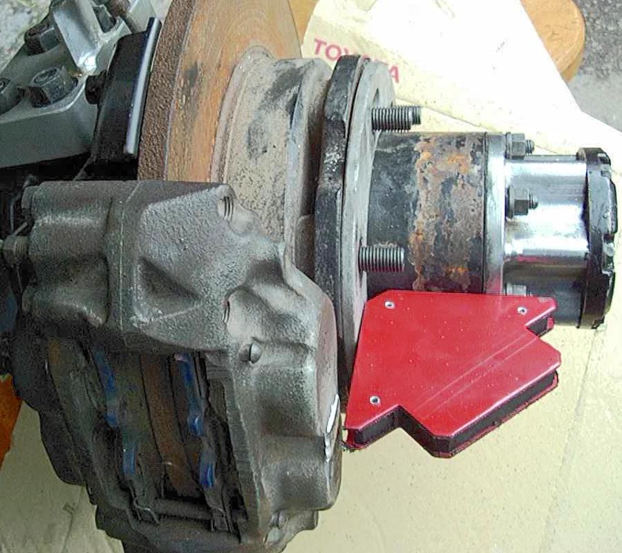
Remove the original ball joint hardware.
- Knock the studs out of the ball joint with a small hammer.
- This is done most easily if the joint is pressed against the arm supported with a floor jack, as shown below.
- Unbolt the upper shock hardware.
-
If you have greaseable ball joints, this is a good time to give them a
shot of lubrication.
- Also, if needed, you can swap out an angled grease fitting for a straight one to allow for later greasing.
- Best to check the access to the grease fitting with your grease gun prior to buttoning up the install in case you need to change the grease fitting out.
 |
| Trimming around upper ball joint |
 |
| Closeup of trimmed upper control arm. |
-
If needed, trim the inner lip of the upper control arm (UCA) as
depicted in the above pictures.
- An angle grinder with a cut-off wheel or a small reciprocating saw works well for this task.
-
How much to trim?
- Just enough to allow installation of the spacer, typically about 1/2". And be sure to leave rounded corners on any of the cuts done to minimize any chances of stress risers in sharp corners, as shown above. You would want to smooth the sharp corners in the above cuts.
- Shorter, custom height, ball joint spacers may require less trimming, or none at all.
-
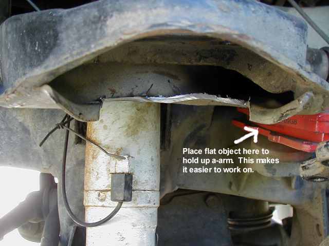
Alternately, you may be able to bend the lip of the UCA with a
hand-held sledge hammer.
- The metal bent or removed is simply excess metal left from forming the shape of the UCA at the factory.
 |
| Ball Joint Spacer Installation |
-
Put the spacer in place, NOTCH FACING DOWNWARD and, using a floor jack
to control arm height, align the ball joint and install the hardware.
- The notch acts as a weep hole to let any water that gets in from above drain out to prevent the ball joint from rusting out.
- If needed, you can remove the upper ball joint from the steering knuckle before installing it under the spacer to have a little more working room if you find the installed ball joint won't go into place.
- If you find the steering spindle will not push back in far enough to line up the ball joint mounting bolts, you might have over extended the CV axle, pulling the inner (plunge) joint out far enough to bind. No worries, just rotate the axle shaft back and forth while pushing on the spindle, it should slide back once things line up and the binding is freed.
- If installing a stacked set of spacers, put the smaller spacer on top of the full height spacer since the smaller spacer will not have the drainage notch machined in it.
-
Also, with the stacked spacers, the hardware is designed to be extra
long in order to get as much unthreaded bolt shank inside the stacked
spacers for the maximum strength. As such, there may be some unthreaded
bolt sticking out beyond the spacers and control arm.
- If this happens, just install a extra washer or two to take up the additional bolt length. The additional washers will not weaken the connection, in fact more than one washer adds to the joint strength.
-
It usually works best to insert the allen head bolts from below since
it allows easier access to tighten the nuts:
-
We now supply a flanged class 10 nylock nut for easier installation
that's just as strong as the previous double nut setup.
- Note that the factory torque specs on the upper and lower ball joints are different
- Tighten fasteners alternately in an X pattern to assure even tightening, torque to 20-25 ft.lb. or 26-35 N.m. with dry threads
- With the supplied flanged nut, the nylock feature will prevent it from loosening.
- If you wish, you can spray the exposed head and threads of the bolts with some paint, as the black oxide coated hardware may tend to rust over time. Or, you can hit the exposed parts of those bolts with a shot of oil periodically. That's how black oxide finish is supposed to be maintained.
-
We now supply a flanged class 10 nylock nut for easier installation
that's just as strong as the previous double nut setup.
-
Extend the shock to see if it needs shimming.
- Place the appropriate number of washers to ensure the shock does not limit down travel.
- Or if you plan to replace the old shock with a new, longer version, do that now.
- Tighten shock hardware.
- Repeat for other side.
-
Re-install the wheels.
-
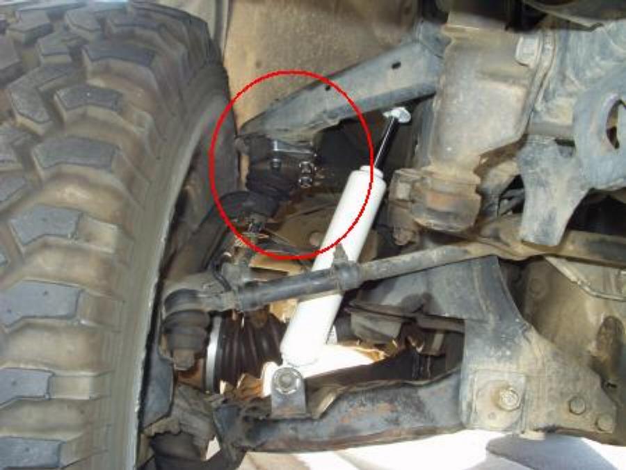
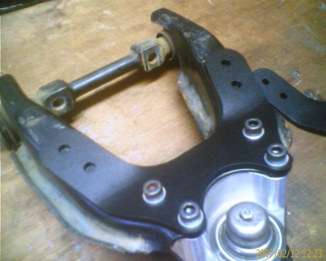
If the end of the upper control arm is too close to the tire at this
point, there are several options:
- You can try and grind off part of the outer lip of the control arm (area at the left edge of the red circle in the photo above)
- You can add a 1/4" wheel spacer to move the wheel/tire away from the suspension.
- You can swap to a narrower tire, for example changing from a 33x12.50 to a 33x10.50 tire will move the inner edge of the tire away from the control arm since it'll have less sidewall bulge on the same wheel.
- You can swap to a wheel with less back side spacing, for example going from a 4.75" to a 4.5" backspaced wheel will move the inner edge of the wheel and tire 1/4" away from the control arm (stock wheels are ~4.75" backspacing).
-
If the end of the upper control arm is too close to the tire at this
point, there are several options:
- Put the vehicle back on the ground.
-
For low profile bump stops only:
- Shim them approx. 1/2" with some washers or use stock bump stops.
- Failure to do so could result in damage to CV joints, shocks, or other components.
-
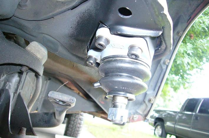
Low profile bump stops are typically made of polyurethane and will be
colored red or some other color as shown below.
- Stock bump stops are typically a black runner material by comparison.
| Shimming for low profile bump stops |
-
Even with stock bump stops, you may experience some CV axle binding.
-
To check, let the suspension hang at full droop.
- Easy to do this when you finish installing the spacers, as the front end should be up in the air.
-
Rotate each CV axle shaft by hand and check for any binding at the CV
joints and also check with the wheels turned to the steering stops in
each direction.
- Also, you may want to feel the CV axle rotation before installing the spacers, just to familiarize yourself with what they feel like "normally".
-
If felt, several options to fix it are available:
- Add some shims as shown above for the low profile bump stops.
- Or install a front differential drop kit to lower the differential and thus lessen the CV joint angles.
-
You can also shim the compression bump stops to limit compression
travel if you goal is to prevent front tire rubbing.
- Since the bump stops are in closer to the frame, even a small amount of shims can help limit upward wheel travel in cases of tires rubbing on the fender at full compression.
- You can also trim or hammer back the sheet metal that the tires are rubbing on.
-
To check, let the suspension hang at full droop.
-
Re-adjust torsion bars, if needed
- If the ride height is what you want it to be after installing the ball joint spacers, there is no need to make any adjustments.
-
There are good instructions on the
4x4Wire.com Toyota page. and a separate
write up on the OffRoad.com Toyota page:
In short:- Spray the torsion bar hardware with a penetrating lubricant.
- Wipe all debris off of the threads.
- Spray them again.
- Jack up the front to unload the bars.
- Adjust them with a 22mm wrench.
- Lower the truck.
- Bounce the front end and roll the truck back and forth at least 10 feet.
-
Repeat until the front is level and at desired height.
- The measurement between the fender lip and edge of rim should be about 15 - 15.5".
- This would be the case for 1.5" lift, stock height is 13.5" - 14".
- NOTE: Adjusting the torsion bars up or down is not the same as adjusting the camber angle, that is done as part of a front end alignment, as described below:
-
- The Toyota IFS front suspension is fully adjustable, for both caster and camber angles (via the lower control arm eccentric adjustment bolts) as well as toe-in, via the tie rod end adjustment.
- It has been observed that some driveway alignment adjusting is beneficial and easy to do.
-
Following these simple steps will make life easier for the alignment
tech who, to be honest, might not be prepared for a vehicle that is any
other than bone stock and only slightly out of alignment.
-
And you may find there are two basic types of alignment shops, one with
the nice shiny computerized machine and the other place where the
mechanic actually has grease under his fingernails and all over his
overalls.
- The former shop might just throw their hands up in the air and tell you it is impossible to align your truck due to the lift, as they have no place to punch in the numbers on their shiny computer.
- The latter shop will typically be able to get a perfect alignment, assuming your front end is not otherwise damaged. They will work with the factory alignment specs and the lift and adjust things to make it all work.
-
So if you are having a shop do your alignment, and the first one you go
to tells you "No way", simply check the phone book for
another shop and go there.
- The reason is that this shop just is out for an easy buck and wants to do the quick tie rod end adjustment for toe in and send you on your way. The proper way to adjust the alignment, as shown below), is to set the caster and camber with the eccentric bolts in the control arms, then set the too in with the tie rod ends. This does take some time to do right, partly because you are changing multiple measurements with one adjustment. And this time costs the shop money and takes some skill, both of which the shop may be short on.
- And if a shop tells you that they could not align your truck, ask them to point to what they tried to adjust. If they point to the tie rods or the torsion bar adjusters (and not to the LCA eccentric bolts), that is a good clue that you might want to find another shop because this shop has no clue what they are doing!!! We know we would not want them working on our truck!
-
And you may find there are two basic types of alignment shops, one with
the nice shiny computerized machine and the other place where the
mechanic actually has grease under his fingernails and all over his
overalls.
-
First make sure the ride height is set to where you want it.
- If not, adjust it with the torsion bar adjusters now
- Loosen the adjustment cams on the lower a-arms making a note of each bolt's orientation.
-
Move the lower arms outward until two things happen.
- (It will likely be necessary to lift the front end while adjusting and roll the truck forward and backward after each adjustment.) One, the tires appear vertical.
- Two, all cams are adjusted to mirror those on the opposing arm and in a position *closely* relative to where they started. (It is more important that the tires be vertical than the hardware be exactly relative to it's originating position)
- For example, if the driver's side front cam is pointing straight up and the driver's side rear cam is pointing outward, the passenger side front cam should be straight up and rear outward.
- If, before adjustment, say the rears were angles outward 30 degrees more than the front, after adjustment the rears should still be outward about 30 degrees. Again this is not as critical as trying to get the tires vertical.
-
Adjust the toe by loosening the adjusters and rotating.
- It is a good idea to lock the steering wheel in a straight position.
- What you adjust to one side, do to the other. Typically about .5-.25" of toe is fine.
- If you have trouble measuring, simply attempt to get them straight or angling in slightly.
-
You'd be surprised how close one can get these measurements with just
the eye.
- However, perfection is not necessary, this will simply get you in the ball part and help to avoid the "blank stare" when an alignment tech sees his numbers are out and doesn't know which nut to turn which way. (you'd be surprised how often this happens with 4X4s)
-
You should recheck the height after this.
- If you find you adjust the height severely, which is unlikely, and the tires are clearly off (by the eye), repeat these steps.
-
Here
is a link to a description of a DIY / driveway alignment procedure.
- And here are detailed 4WD alignment instructions from the Factory Service Manual.
-
A visit to an alignment shop is definitely recommended if you're uncomfortable
doing it yourself.
- You may need to shop around for a good alignment shop as some may tell you they can't align the truck because it is "modified".
- Don't be "wowed" by the shop with the fanciest computerized equipment, either. You may find the technicians at such shops may throw up their hands if the computer says the alignment is too far out.
- Look for a local "mom and pop" shop when they will actually understand how to align the front end and are willing to work with the available adjustments and make it work. There should be adequate adjustment range in the front suspension adjusting cams to handle the ball joint spacers and changed ride height, assuming the front end is not damaged.
- If you find you can't get the camber adjusted into spec. above a certain amount of lift, then the ride height at which you can adjust the camber properly is the limit of how high you can go.
-
Re-check hardware torque in 2 weeks.
- If you are running the extra tall stacked spacers and are satisfied with the height, you can use a metal epoxy adhesive to joint the two spacers together if you want to ensure that there is no slippage between the two spacers. Simply remove the spacers, lightly sand the mating surfaces (we purposely leave one face of the smaller spacer slightly rough for better bonding) and thoroughly clean and degrease the mating surfaces and then apply a thin film of adhesive, install and tighten down the bolts to clamp the spacers together. After the adhesive cures, you should be good to go.
- If you find problems with your CV joints binding due to the steeper angles or find the CV joint boots rubbing and wearing out faster, you might consider adding a front differential drop kit.
Easier CV axle replacement modification:
While not really related to ball joint spacers (or a front differential drop kit), many owners find that replacing front CV axle half shafts is a difficult process. Mainly this is due to the tight location in which the axles are installed. Often, you can loosen the lower ball joint clamp and swing the lower control arm out of the way (disconnect the front sway bar if installed) and then swing the spindle/hub up out of the way for more clearance when removing or installing the CV axle. Here is a write-up on a simple modification that can help in future replacement that involves replacing the differential output flange studs with bolts:
[Return to the top of this page]2WD Ball Joint Spacer Installation:
-
If you are planning to do a Driveway
Alignment after installing the spacers, it might be a good idea
to set up and check your alignment before you install the spacers.
- This way you'll know what things are "supposed" to look like when set up properly, since assuming your vehicle drives OK now, it is likely reasonably well aligned.
- You'll know if you are capable of performing the alignment yourself
-
Block the rear wheels and place the front end of the truck on jack
stands and remove the front wheels.
- Let the front suspension fully droop, tire should spin freely.
- Loosen ball joint hardware, ball joint will drop off of the arm (photo A below)
- Remove old ball joint hardware
- Place spacer on top of the ball joint, slowly lower the jack to assist in lining up bolts with the hole (photo B below)
-
It usually works best to insert the allen head bolts from below since
it allows easier access to tighten the nuts:
-
We now supply a flanged class 10 nylock nut for easier installation
that's just as strong as the previous double nut setup.
- Tighten fasteners alternately in an X pattern to assure even tightening, torque to 20-25 ft.lb. or 26-35 N.m. with dry threads
- With the supplied flanged nut, the nylock feature will prevent it from loosening.
- If you wish, you can spray the exposed head and threads of the bolts with some paint, as the black oxide coated hardware may tend to rust over time. Or, you can hit the exposed parts of those bolts with a shot of oil periodically. That's how black oxide finish is supposed to be maintained.
-
We now supply a flanged class 10 nylock nut for easier installation
that's just as strong as the previous double nut setup.
- Do the other side.
- Lower vehicle.
- If you decide to adjust the torsion bars up or down for more or less lift, do so now.
- If you decide to shim the shocks, do so now.
-
Get an alignment:
-
The 2WD trucks use shims to adjust the caster and camber as noted
below:
- Caster and camber are adjusted by increasing or decreasing the number of shims between upper arm shaft and frame mounting surface.
- The thickness difference between front and rear shim packs should not exceed 0.16 inch (4mm).
- If you find the camber angle is too much, try lowering the ride height by adjusting the torsion bar pre-load to lower the front end.
- Here are detailed 2WD alignment instructions
-
The 2WD trucks use shims to adjust the caster and camber as noted
below:
- Check tightness of bolts after a week.
 |
||
| A: Upper Ball Joint removed | B: Spacer and Ball Joint Reinstalled | C: Upper Control Arm Brace |
Upper Control Arm Brace Installation:
For the upper control arm (UCA) brace, you want to bolt it on top of the UCA with the 4 - 8mm ball joint bolts. Then in the remaining holes (4 in total), mark and drill holes through the UCA to accommodate the supplied 6mm bolts and then bolt the brace on top of the UCA. You can see the 4 bolt holes, 2 per side, in photo C above. Be sure to get all 8 bolts installed before tightening down any of them. Tighten down the ball joint bolts per factory specification and then tighten the 4 - 6mm bolts to approx. 10-15 ft.lb.
The 2WD upper control arm braces can be installed with stock ball joints (without the spacers) as well. If the existing ball joint studa have at least 1/4 inch of thread exposed, you can re-use those. Otherwise, pick up a set of 8 M8x25 or 5/16x1 inch bolts and nuts (class 10.9 or grade 8 recommended) and use those to replace the existing ball joint studs. If you can't locate any hardware, order a set here. Order the 0.5 inch hardware option as that'll work with the 0.25 inch thick braces.
[Return to the top of this page]
Visitor # since 25.AUG.2005
[Last updated: 05.July.2026]
The latest version of this document may be found at: /4x4/ForSale/Docs/BallJointSpacer_HowTo.shtml